MSI Z270 SLI Plus, Z270 SLI v2 Quick Start Guide
1Unpacking
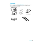
Unpacking Thank you for buying the MSI Z270 SLI PLUS/ Z270 SLI motherboard. Check to make sure your motherboard box contains the following items. If something is missing, contact your dealer as soon as possible.
SATA Cable x2
Drivers & Utilities Disc Motherboard User
Guide
I/O Shield
Motherboard
2 Safety Information
Safety Information y The components included in this package are prone to damage from electrostatic discharge (ESD). Please adhere to the following instructions to ensure successful computer assembly.
y Ensure that all components are securely connected. Loose connections may cause the computer to not recognize a component or fail to start.
y Hold the motherboard by the edges to avoid touching sensitive components. y It is recommended to wear an electrostatic discharge (ESD) wrist strap when handling the motherboard to prevent electrostatic damage. If an ESD wrist strap is not available, discharge yourself of static electricity by touching another metal object before handling the motherboard.
y Store the motherboard in an electrostatic shielding container or on an anti-static pad whenever the motherboard is not installed.
y Before turning on the computer, ensure that there are no loose screws or metal components on the motherboard or anywhere within the computer case.
y Do not boot the computer before installation is completed. This could cause permanent damage to the components as well as injury to the user.
y If you need help during any installation step, please consult a certified computer technician.
y Always turn off the power supply and unplug the power cord from the power outlet before installing or removing any computer component.
y Keep this user guide for future reference. y Keep this motherboard away from humidity. y Make sure that your electrical outlet provides the same voltage as is indicated on the PSU, before connecting the PSU to the electrical outlet.
y Place the power cord such a way that people can not step on it. Do not place anything over the power cord.
y All cautions and warnings on the motherboard should be noted. y If any of the following situations arises, get the motherboard checked by service personnel: Liquid has penetrated into the computer. The motherboard has been exposed to moisture. The motherboard does not work well or you can not get it work according to user guide.
The motherboard has been dropped and damaged. The motherboard has obvious sign of breakage.
y Do not leave this motherboard in an environment above 60C (140F), it may damage the motherboard.
3Quick Start
Intel LGA 1151 CPU
DDR4 Memory
Graphics CardSATA Hard Disk DriveSATA DVD Drive
A Package of ScrewsPhillips Screwdriver
Chassis
Power Supply Unit
CPU Fan Thermal Paste
Quick Start Preparing Tools and Components
4 Quick Start
http://youtu.be/bf5La099urI
Installing a Processor
1
2
3
6
4 5
7
8
9
5Quick Start
1
1
2
2
3
3
Installing DDR4 memory
http://youtu.be/T03aDrJPyQs
DIMMB2 DIMMB2 DIMMB1
DIMMA2 DIMMA2 DIMMA2 DIMMA1
6 Quick Start
Connecting the Front Panel Header
http://youtu.be/DPELIdVNZUI
1
2 10
9
JFP1
1 HDD LED + 2 Power LED +
3 HDD LED - 4 Power LED -
5 Reset Switch 6 Power Switch
7 Reset Switch 8 Power Switch
9 Reserved 10 No Pin
RE SE
T S W
PO WER
SW
POWER LED+ POWER LED-
HDD LED
HD D L
ED RE
SE T S
W
JFP1
HDD LED HDD LED - HDD LED +
POWER LED - POWER LED +
POWER LED
7Quick Start
Installing the Motherboard
1
2
8 Quick Start
Installing SATA Drives
http://youtu.be/RZsMpqxythc 1
2 3
4
5
9Quick Start
1
Installing a Graphics Card
http://youtu.be/mG0GZpr9w_A
2
3
4
5
6
10 Quick Start
Connecting Peripheral Devices
11Quick Start
Connecting the Power Connectors
http://youtu.be/gkDYyR_83I4
ATX_PWR1 CPU_PWR1
12 Quick Start
Power On
1
4
2
3
13Contents
Contents Unpacking .............................................................................................................. 1
Safety Information ................................................................................................. 2
Quick Start ............................................................................................................. 3 Preparing Tools and Components .......................................................................... 3 Installing a Processor ............................................................................................. 4 Installing DDR4 memory ........................................................................................ 5 Connecting the Front Panel Header ....................................................................... 6 Installing the Motherboard ..................................................................................... 7 Installing SATA Drives............................................................................................. 8 Installing a Graphics Card ...................................................................................... 9 Connecting Peripheral Devices ............................................................................ 10 Connecting the Power Connectors ....................................................................... 11 Power On............................................................................................................... 12
Specifications ....................................................................................................... 15
Block Diagram .................................................................................................... 20
Rear I/O Panel ..................................................................................................... 21 LAN Port LED Status Table................................................................................... 21 Audio Ports Configuration .................................................................................... 21 Realtek HD Audio Manager .................................................................................. 22
Overview of Components .................................................................................... 24 CPU Socket ........................................................................................................... 26 DIMM Slots ............................................................................................................ 27 PCI_E1~6: PCIe Expansion Slots .......................................................................... 28 M2_1~2: M.2 Slots (Key M) ................................................................................... 30 SATA1~6: SATA 6Gb/s Connectors ....................................................................... 31 JFP1, JFP2: Front Panel Connectors ................................................................... 32 CPU_PWR1, ATX_PWR1: Power Connectors ....................................................... 33 JCOM1: Serial Port Connector ............................................................................. 33 JUSB1~2: USB 2.0 Connectors ............................................................................. 34 JUSB3~4: USB 3.1 Gen1 Connectors ................................................................... 34 CPU_FAN1,SYS_FAN1~4, PUMP_FAN1: Fan Connectors .................................... 35 JAUD1: Front Audio Connector ............................................................................ 36 JCI1: Chassis Intrusion Connector ....................................................................... 36 JTPM1: TPM Module Connector ........................................................................... 37 JBAT1: Clear CMOS (Reset BIOS) Jumper ........................................................... 37 JLED1: RGB LED connector ................................................................................. 38
14 Contents
JLPT1: Parallel Port Connector ........................................................................... 38
Onboard LEDs ...................................................................................................... 39 EZ Debug LEDs ..................................................................................................... 39
BIOS Setup ........................................................................................................... 40 Entering BIOS Setup ............................................................................................. 40 Resetting BIOS ...................................................................................................... 41 Updating BIOS ....................................................................................................... 41 EZ Mode ................................................................................................................ 42 Advanced Mode .................................................................................................... 44 SETTINGS .............................................................................................................. 45 Advanced ............................................................................................................... 45 Boot ....................................................................................................................... 52 Security ................................................................................................................. 53 Save & Exit ............................................................................................................ 54 OC .......................................................................................................................... 55 M-FLASH .............................................................................................................. 61 OC PROFILE .......................................................................................................... 62 HARDWARE MONITOR .......................................................................................... 63
Software Description ........................................................................................... 64 Installing Windows 7/ 8.1/ 10.............................................................................. 64 Installing Drivers .................................................................................................. 64 Installing Utilities ................................................................................................. 64 LIVE UPDATE 6 ...................................................................................................... 65 COMMAND CENTER ............................................................................................. 67 MSI SMART TOOL ................................................................................................. 71 MYSTIC LIGHT ....................................................................................................... 73 RAMDISK............................................................................................................... 74 X-BOOST ............................................................................................................... 75 NETWORK MANAGER ........................................................................................... 77 Intel Extreme Tuning Utility ................................................................................ 79 CPU-Z.................................................................................................................... 80
RAID Configuration .............................................................................................. 81 Using Intel Rapid Storage Technology Option ROM ........................................... 81 Degraded RAID Array ........................................................................................... 84 M.2 PCIe SSD RAID ............................................................................................... 86
Troubleshooting .................................................................................................. 88
Regulatory Notices .............................................................................................. 89
15Specications
Specifications
CPU y Supports 7th/6th Gen Intel Core i3/i5/i7 processors, and Intel Pentium and Celeron processors for Socket LGA1151
Chipset Intel Z270 Chipset
Memory
y 4x DDR4 memory slots, support up to 64GB 7th processors support DDR4 3800(OC)/ 3600(OC)/ 3200(OC)/ 3000(OC)/ 2800(OC)/ 2600(OC)/ 2400/ 2133 MHz*
6th processors support DDR4 3600(OC)/ 3200(OC)/ 3000(OC)/ 2800(OC)/ 2600(OC)/ 2400(OC)/ 2133 MHz*
y Dual channel memory architecture y Supports non-ECC, un-buffered memory y Supports Intel Extreme Memory Profile (XMP) *Please refer to www.msi.com for more information on compatible memory.
Expansion Slots y 3x PCIe 3.0 x16 slots (support x16/x0/x4, x8/x8/x4 modes) y 3x PCIe 3.0 x1 slots
Onboard Graphics
y 1x HDMI port, supports a maximum resolution of 4096x2160@30Hz(7th CPU), 4096x2160@24Hz(6th CPU), 2560x1600@60Hz
y 1x DVI-D port, supports a maximum resolution of 1920x1200@60Hz
Multi-GPU y Supports 2-Way NVIDIA SLI Technology y Supports 3-Way AMD CrossFire Technology
Storage
Intel Z270 Chipset y 6x SATA 6Gb/s ports* y 2x M.2 slots (Key M)
Support up to PCIe 3.0 x4 and SATA 6Gb/s Support PCIe 3.0 x4 NVMe U.2 SSD with Turbo U.2 Host Card**
M2_1 slot supports 2242/ 2260 /2280/ 22110 storage devices
M2_2 slot supports 2242/ 2260 /2280 storage devices Intel Optane Memory Ready for all M.2 slots
y Supports Intel Smart Response Technology for Intel Core processors
* The SATA1, SATA5 and SATA6 ports will become unavailable with some conditions of M.2 devices. Please refer to page 31 for M.2 & SATA combination table.
** The Turbo U.2 Host Card is not included, please purchase separately.
Continued on next page
16 Specications
Continued from previous page
RAID
Intel Z270 Chipset y Supports RAID 0, RAID 1, RAID 5 and RAID 10 for SATA storage devices
y Supports RAID 0 and RAID 1 for M.2 storage devices* * M.2 PCIe RAID volume can be created with M.2 GENIE. Please refer to page
43 for details about M.2 GENIE.
USB
y ASMedia ASM2142 Chipset 1x USB 3.1 Gen2 (SuperSpeed USB 10Gbps) Type-C port on the back panel
1x USB 3.1 Gen2 (SuperSpeed USB 10Gbps) Type-A port on the back panel
y Intel Z270 Chipset 8x USB 3.1 Gen1 (SuperSpeed USB) ports (4 Type-A ports on the back panel, 4 ports available through the internal USB connectors)
6x USB 2.0 (High-speed USB) ports (2 Type-A ports on the back panel, 4 ports available through the internal USB connectors)
Audio y Realtek ALC1220 Codec y 7.1-Channel High Definition Audio
LAN 1x Intel I219-V Gigabit LAN controller
Back Panel Connectors
y 1x PS/2 mouse & keyboard combo port y 2x USB 2.0 ports y 1x DVI-D port y 1x USB 3.1 Gen2 Type-A port y 1x USB 3.1 Gen2 Type-C port y 4x USB 3.1 Gen1 Type-A ports y 1x HDMI port y 1x LAN (RJ45) port y 6x audio jacks
Internal Connectors
y 1x 24-pin ATX main power connector y 1x 8-pin ATX 12V power connector y 6x SATA 6Gb/s connectors y 2x USB 3.1 Gen1 connectors (supports additional 4 USB 3.1 Gen1 ports)
y 2x USB 2.0 connectors (supports additional 4 USB 2.0 ports)
y 1x 4-pin CPU fan connector y 1x 4-pin water pump fan connector y 4x 4-pin system fan connectors
Continued on next page
17Specications
Continued from previous page
Internal Connectors
y 1x Front panel audio connector y 2x Front panel connectors y 1x RGB LED connector (Z270 SLI PLUS) y 1x TPM module connector y 1x Chassis Intrusion connector y 1x Serial port connector y 1x Parallel port connector y 1x Clear CMOS jumper
I/O Controller NUVOTON NCT6795 Controller Chip
Hardware Monitor y CPU/System temperature detection y CPU/System fan speed detection y CPU/System fan speed control
From Factor y ATX Form Factor y 12.0 in. x 9.6 in. (30.5 cm x 24.4 cm)
BIOS Features
y 1x 128 Mb flash y UEFI AMI BIOS y ACPI 5.0, PnP 1.0a, SM BIOS 2.8 y Multi-language
Software
y Drivers y COMMAND CENTER y LIVE UPDATE 6 y FAST BOOT y SUPER CHARGER y MYSTIC LIGHT y RAMDISK y X-BOOST y MSI SMART TOOL y CPU-Z MSI GAMING y NETWORK MANAGER y Intel Extreme Tuning Utility y Norton Internet Security Solution y Google Chrome, Google Toolbar, Google Drive
Continued on next page
18 Specications
Continued from previous page
MSI Exclusive Features
y CLICK BIOS 5 EZ Mode & Advanced Mode Switching Board Explorer Hardware Monitor
y MILITARY CLASS 5 Military Class Component Military Class Stability and Reliability
ESD Protection EMI Protection Humidity Protection Circuit Protection High Temperature Protection VGA Armor Slot
y MSI Steel Armor PCI-E Steel Armor DDR4 Steel Shielding
y COMMAND CENTER System Monitor Smart Fan Control
y MYSTIC LIGHT EXTENSION (Z270 SLI PLUS) Dedicated HEADER for 4-pin RGB-strip LIGHT CONTROL
y RAMDISK y LIVE UPDATE 6 y VR BOOST y X-BOOST
System Performance Enhancement User Scenario Profile
Continued on next page
19Specications
Continued from previous page
Specification Highlights
y DDR4 Boost Support Dual-Channel DDR4 Memory Support Isolated DDR4 Circuit Design DDR4 XMP Ready
y PCI Express 3.0 Support 2-Way Nvidia SLITM Support 3-Way AMD CrossFireTM Support
y USB 3.1 Gen2 Ready USB 3.1 Gen2 Type-A Ready USB 3.1 Gen2 Type-C Ready
y Twin Turbo M.2 Ready Dual M.2 RAID Support PCIe 3.0 x4 (32 Gb/s) Support PCIe / SATA Dual Mode Support Intel Optane Memory Ready
y NVMe / AHCI Driver Support y U.2 Support (Optional)
20 Block Diagram
Block Diagram
LPC Bus 2 x USB 3.1 Gen2
2 Channel DDR4 Memory
8 x USB 3.1 Gen1
2 x M.2
6 x USB 2.0
PCI-E Bus
PCI Express Bus
PCI Express Bus
P/S2 Mouse / Keyboard Audio Jacks
DMI 3.0
Z270
CPU
NV6795 Super I/O
Realtek ALC1220
ASMEDIA ASM2142
x1
x1
x4
x2
PCI Express Bus
HDMI DVI-D
Switch
x1
PCIe x1 slot
PCIe x1 slot
PCIe x1 slot
PCIe x4 slot
6 x SATA 6Gb/s
21Rear I/O Panel
Rear I/O Panel
PS/2 Port LAN
USB 2.0
Audio Ports
DVI-D
USB 3.1 Gen1
USB 3.1 Gen2
USB 3.1 Gen1USB 3.1 Gen2 Type-C
Link/ Activity LED
Status Description
Off No link
Yellow Linked
Blinking Data activity
Speed LED
Status Description
Off 10 Mbps connection
Green 100 Mbps connection
Orange 1 Gbps connection
LAN Port LED Status Table
Audio Ports Configuration
Audio Ports Channel
2 4 6 8
Rear Speaker Out
Center/ Subwoofer Out
Side Speaker Out
Mic In
Line-Out/ Front Speaker Out
Line-In
(: connected, Blank: empty)
22 Rear I/O Panel
Realtek HD Audio Manager After installing the Realtek HD Audio driver, the Realtek HD Audio Manager icon will appear in the system tray. Double click on the icon to launch.
Jack Status
Device Selection
Connector Strings
Profiles
Main Volume
Application Enhancement
Advanced Settings
y Device Selection - allows you to select a audio output source to change the related options. The check sign indicates the devices as default.
y Application Enhancement - the array of options will provide you a complete guidance of anticipated sound effect for both output and input device.
y Main Volume - controls the volume or balance the right/left side of the speakers that you plugged in front or rear panel by adjust the bar.
y Profiles - toggles between profiles. y Advanced Settings - provides the mechanism to deal with 2 independent audio streams.
y Jack Status - depicts all render and capture devices currently connected with your computer.
y Connector Settings - configures the connection settings.
Auto popup dialog When you plug into a device at an audio jack, a dialogue window will pop up asking you which device is current connected.
Each jack corresponds to its default setting as shown on the next page.
23Rear I/O Panel
AUDIO INPUT
Rear
Front
Side
Center/ Subwoofer
Audio jacks to headphone and microphone diagram
Audio jacks to stereo speakers diagram
Audio jacks to 7.1-channel speakers diagram
AUDIO INPUT
24 Overview of Components
Overview of Components
PCI_E1
PCI_E2
JCOM1
JLED1 (optional)
PCI_E3
PCI_E4
PCI_E5
PCI_E6
CPU Socket
CPU_PWR1
ATX_PWR1
JUSB3
JUSB1
JUSB2
JBAT1
JUSB4
SATA12 SATA3 SATA4
SATA56
M2_1
M2_2
DIMMA1
DIMMA2 DIMMB1
DIMMB2
SYS_FAN1
SYS_FAN4
SYS_FAN3
JCI1
JFP1 JFP2
CPU_FAN1
PUMP_FAN1
JTPM1
JLPT1
SYS_FAN2
JAUD1
25Overview of Components
Component Contents
Port Name Port Type Page
CPU_FAN1,SYS_FAN1~4, PUMP_FAN1 Fan Connectors 35
CPU_PWR1, ATX_PWR1 Power Connectors 33
CPU Socket LGA1151 CPU Socket 26
DIMMA1, A2, B1, B2 DIMM Slots 27
JAUD1 Front Audio Connector 36
JBAT1 Clear CMOS (Reset BIOS) Jumper 37
JCI1 Chassis Intrusion Connector 36
JCOM1 Serial Port Connector 33
JFP1, JFP2 Front Panel Connectors 32
JLED1 RGB LED connector 38
JLPT1 Parallel Port Connector 38
JTPM1 TPM Module Connector 37
JUSB1~2 USB 2.0 Connectors 34
JUSB3~4 USB 3.1 Gen1 Connectors 34
M2_1~2 M.2 Slots (Key M) 30
PCI_E1~6 PCIe Expansion Slots 28
SATA1~6 SATA 6Gb/s Connectors 31
26 Overview of Components
CPU Socket
Introduction to the LGA 1151 CPU The surface of the LGA 1151 CPU has two notches and a golden triangle to assist in correctly lining up the CPU for motherboard placement. The golden triangle is the Pin 1 indicator.
Important
y Always unplug the power cord from the power outlet before installing or removing the CPU.
y Please retain the CPU protective cap after installing the processor. MSI will deal with Return Merchandise Authorization (RMA) requests if only the motherboard comes with the protective cap on the CPU socket.
y When installing a CPU, always remember to install a CPU heatsink. A CPU heatsink is necessary to prevent overheating and maintain system stability.
y Confirm that the CPU heatsink has formed a tight seal with the CPU before booting your system.
y Overheating can seriously damage the CPU and motherboard. Always make sure the cooling fans work properly to protect the CPU from overheating. Be sure to apply an even layer of thermal paste (or thermal tape) between the CPU and the heatsink to enhance heat dissipation.
y Whenever the CPU is not installed, always protect the CPU socket pins by covering the socket with the plastic cap.
y If you purchased a separate CPU and heatsink/ cooler, Please refer to the documentation in the heatsink/ cooler package for more details about installation.
y This motherboard is designed to support overclocking. Before attempting to overclock, please make sure that all other system components can tolerate overclocking. Any attempt to operate beyond product specifications is not recommended. MSI does not guarantee the damages or risks caused by inadequate operation beyond product specifications.
27Overview of Components
DIMM Slots
DIMMA1 DIMMB1
Channel A Channel B
DIMMA2 DIMMB2
Memory module installation recommendation
DIMMB2 DIMMB2 DIMMB1
DIMMA2 DIMMA2 DIMMA2 DIMMA1
Important
y Always insert memory modules in the DIMMA2 slot first. y Due to chipset resource usage, the available capacity of memory will be a little less
than the amount of installed. y Based on Intel CPU specification, the Memory DIMM voltage below 1.35V is
suggested to protect the CPU. y Please note that the maximum capacity of addressable memory is 4GB or less
for 32-bit Windows OS due to the memory address limitation. Therefore, we recommended that you to install 64-bit Windows OS if you want to install more than 4GB memory on the motherboard.
y Some memory may operate at a lower frequency than the marked value when overclocking due to the memory frequency operates dependent on its Serial Presence Detect (SPD). Go to BIOS and find the Memory Try It! to set the memory frequency if you want to operate the memory at the marked or at a higher frequency.
y It is recommended to use a more efficient memory cooling system for full DIMMs installation or overclocking.
y The stability and compatibility of installed memory module depend on installed CPU and devices when overclocking.
28 Overview of Components
PCI_E1~6: PCIe Expansion Slots
PCI_E1: PCIe 3.0 x16
PCI_E2: PCIe 3.0 x1
PCI_E3: PCIe 3.0 x1
PCI_E4: PCIe 3.0 x8
PCI_E5: PCIe 3.0 x1
PCI_E6: PCIe 3.0 x4
x16 x8 x8
x8 x8 x4
Multiple graphics cards installation recommendation
Important
If you install a large and heavy graphics card, you need to use a tool such as MSI Gaming Series Graphics Card Bolster to support its weight and to prevent deformation of the slot.
29Overview of Components
Important
y For a single PCIe x16 expansion card installation with optimum performance, using the PCI_E1 slot is recommended.
y When adding or removing expansion cards, always turn off the power supply and unplug the power supply power cable from the power outlet. Read the expansion cards documentation to check for any necessary additional hardware or software changes.
Installing SLI graphics cards For power supply recommendations for SLI configurations, please refer to the user guide of your graphics card to make sure you meet all the system requirements. To install SLI graphics cards: 1. Turn off your computer and disconnect the power cord, install two graphics cards
into the PCI_E1 and PCI_E4 slots. 2. Connect the two cards together using the SLI Bridge Connector.
3. Connect all PCIe power connectors of the graphics cards. 4. Reconnect the power cord, power up the computer and install the drivers and
software included in your graphics card package. 5. Right-click the Windows desktop and select NVIDIA Control Panel from the menu,
click on Configure SLI, Surround, PhysX in the left task pane and select Maximize 3D performance in the SLI configuration menu, and then click Apply.
30 Overview of Components
Important
y Intel RST only supports PCIe M.2 SSD with UEFI ROM. y Intel OptaneTM Memory Ready for all M.2 slots.
Video Demonstration
Watch the video to learn how to Install M.2 module. http://youtu.be/JCTFABytrYA
M2_1~2: M.2 Slots (Key M)
M2_1
M2_2
Installing M.2 module
1
2
3 30
3. Tighten the base screw into the hole of the distance to the M.2 slot as the length your M.2 module.
4. Insert your M.2 module into the M.2 slot at a 30-degree angle.
5. Put the screw in the notch on the trailing edge of your M.2 module and tighten it into the base screw.
1. Remove the screw from the base screw.
2. Remove the base screw.
4
5
31Overview of Components
SATA1~6: SATA 6Gb/s Connectors These connectors are SATA 6Gb/s interface ports. Each connector can connect to one SATA device.
SATA1 SATA2
SATA3
SATA5 SATA6
SATA4
Important
y The SATA1 / SATA5 port will be unavailable when an M.2 SATA SSD module has been installed in the M2_1/ M2_2 slot.
y The SATA5 and SATA6 ports will be unavailable when an M.2 PCIe SSD module has been install in the M2_2 slot.
y Please do not fold the SATA cable at a 90-degree angle. Data loss may result during transmission otherwise.
y SATA cables have identical plugs on either sides of the cable. However, it is recommended that the flat connector be connected to the motherboard for space saving purposes.
M.2 & SATA combination table
Slot Available SATA connectors
M2_1 PCIe SATA PCIe SATA
M2_2 PCIe PCIe SATA SATA
SATA1 SATA2 SATA3 SATA4 SATA5 SATA6
(SATA: M.2 SATA SSD, PCIe: M.2 PCIe SSD, : available, : unavailable)
32 Overview of Components
JFP1, JFP2: Front Panel Connectors These connectors connect to the switches and LEDs on the front panel.
1
2 10
9
JFP1
1 HDD LED + 2 Power LED +
3 HDD LED - 4 Power LED -
5 Reset Switch 6 Power Switch
7 Reset Switch 8 Power Switch
9 Reserved 10 No Pin
1 JFP2
1 Speaker - 2 Buzzer +
3 Buzzer - 4 Speaker +
M.2 slots with examples of various combination possibilities
PCIe SATA
SATA PCIe
PCIe SATA
PCIe SATA
SA TA
4 SA
TA 2
2xM.2 PCIe SSDs + 4xSATA HDDs 2xM.2 SATA SSDs + 4xSATA HDDs
1xM.2 PCIe SSD + 1xM.2 SATA SSD + 5xSATA HDDs
SA TA
3 SA
TA 2
SA TA
1 SA
TA 4
SA TA
3 SA
TA 2
SA TA
4
SA TA
3 SA
TA 2
SA TA
4
SA TA
6 SA
TA 3
SA TA
2
SA TA
1 SA
TA 4
SA TA
6
1xM.2 SATA SSD + 1xM.2 PCIe SSD + 3xSATA HDDs
33Overview of Components
24
131
12
ATX_PWR1
1 +3.3V 13 +3.3V
2 +3.3V 14 -12V
3 Ground 15 Ground
4 +5V 16 PS-ON#
5 Ground 17 Ground
6 +5V 18 Ground
7 Ground 19 Ground
8 PWR OK 20 Res
9 5VSB 21 +5V
10 +12V 22 +5V
11 +12V 23 +5V
12 +3.3V 24 Ground
5 4 1 8 CPU_PWR1
1 Ground 5 +12V
2 Ground 6 +12V
3 Ground 7 +12V
4 Ground 8 +12V
Important
Make sure that all the power cables are securely connected to a proper ATX power supply to ensure stable operation of the motherboard.
CPU_PWR1, ATX_PWR1: Power Connectors These connectors allow you to connect an ATX power supply.
1
2 10
9
1 DCD 2 SIN
3 SOUT 4 DTR
5 Ground 6 DSR
7 RTS 8 CTS
9 RI 10 No Pin
JCOM1: Serial Port Connector This connector allows you to connect the optional serial port with bracket.
34 Overview of Components
JUSB3~4: USB 3.1 Gen1 Connectors These connectors allow you to connect USB 3.1 Gen1 ports on the front panel.
1
10 11
20
1 Power 11 USB2.0+
2 USB3_RX_DN 12 USB2.0-
3 USB3_RX_DP 13 Ground
4 Ground 14 USB3_TX_C_DP
5 USB3_TX_C_DN 15 USB3_TX_C_DN
6 USB3_TX_C_DP 16 Ground
7 Ground 17 USB3_RX_DP
8 USB2.0- 18 USB3_RX_DN
9 USB2.0+ 19 Power
10 NC 20 No Pin
Important
Note that the Power and Ground pins must be connected correctly to avoid possible damage.
JUSB1~2: USB 2.0 Connectors These connectors allow you to connect USB 2.0 ports on the front panel.
1
2 10
9
1 VCC 2 VCC
3 USB0- 4 USB1-
5 USB0+ 6 USB1+
7 Ground 8 Ground
9 No Pin 10 NC
Important
y Note that the VCC and Ground pins must be connected correctly to avoid possible damage.
y In order to recharge your iPad,iPhone and iPod through USB ports, please install MSI SUPER CHARGER utility.
35Overview of Components
CPU_FAN1,SYS_FAN1~4, PUMP_FAN1: Fan Connectors Fan connectors can be classified as PWM (Pulse Width Modulation) Mode or DC Mode. PWM Mode fan connectors provide constant 12V output and adjust fan speed with speed control signal. DC Mode fan connectors control fan speed by changing voltage. When you plug a 3-pin (Non-PWM) fan to a fan connector in PWM mode, the fan speed will always maintain at 100%, which might create a lot of noise. You can follow the instruction below to adjust the fan connector to PWM or DC Mode.
Switching fan mode and adjusting fan speed You can switch between PWM mode and DC mode and adjust fan speed in BIOS > HARDWARE MONITOR.
Select PWM mode or DC mode
Important
Make sure fans are working properly after switching the PWM/ DC mode.
There are gradient points of the fan speed that allow you to adjust fan speed in relation to CPU temperature.
PWM Mode pin definition
1 Ground 2 +12V
3 Sense 4 Speed Control Signal
DC Mode pin definition
1 Ground 2 Voltage Control
3 Sense 4 NC
Pin definition of fan connectors
1
CPU_FAN1
Default PWM Mode fan connectors
Default DC Mode fan connectors
1
SYS_FAN1/ SYS_FAN3/ SYS_FAN4
SYS_FAN2
1
1
PUMP_FAN1
36 Overview of Components
JAUD1: Front Audio Connector This connector allows you to connect audio jacks on the front panel.
1
2 10
9
1 MIC L 2 Ground
3 MIC R 4 NC
5 Head Phone R 6 MIC Detection
7 SENSE_SEND 8 No Pin
9 Head Phone L 10 Head Phone Detection
JCI1: Chassis Intrusion Connector This connector allows you to connect the chassis intrusion switch cable.
Normal (default)
Trigger the chassis intrusion event
Using chassis intrusion detector 1. Connect the JCI1 connector to the chassis intrusion switch/ sensor on the chassis. 2. Close the chassis cover. 3. Go to BIOS > SETTINGS > Security > Chassis Intrusion Configuration. 4. Set Chassis Intrusion to Enabled. 5. Press F10 to save and exit and then press the Enter key to select Yes. 6. Once the chassis cover is opened again, a warning message will be displayed on
screen when the computer is turned on.
Resetting the chassis intrusion warning 1. Go to BIOS > SETTINGS > Security > Chassis Intrusion Configuration. 2. Set Chassis Intrusion to Reset. 3. Press F10 to save and exit and then press the Enter key to select Yes.
37Overview of Components
1
2 14
13
1 LPC Clock 2 3V Standby power
3 LPC Reset 4 3.3V Power
5 LPC address & data pin0 6 Serial IRQ
7 LPC address & data pin1 8 5V Power
9 LPC address & data pin2 10 No Pin
11 LPC address & data pin3 12 Ground
13 LPC Frame 14 Ground
JTPM1: TPM Module Connector This connector is for TPM (Trusted Platform Module). Please refer to the TPM security platform manual for more details and usages.
JBAT1: Clear CMOS (Reset BIOS) Jumper There is CMOS memory onboard that is external powered from a battery located on the motherboard to save system configuration data. If you want to clear the system configuration, set the jumper to clear the CMOS memory.
Keep Data (default)
Clear CMOS/ Reset BIOS
Resetting BIOS to default values 1. Power off the computer and unplug the power cord 2. Use a jumper cap to short JBAT1 for about 5-10 seconds. 3. Remove the jumper cap from JBAT1. 4. Plug the power cord and power on the computer.
38 Overview of Components
Important
y This connector supports 5050 RGB multi-color LED strips (12V/G/R/B) with the maximum power rating of 3A (12V). Please keeping the LED strip shorter than 2 meters to prevent dimming.
y Always turn off the power supply and unplug the power cord from the power outlet before installing or removing the RGB LED strip.
y Please use MYSTIC LIGHT to control the extended LED strip
1
2 26
25
1 RSTB# 2 AFD# 3 PRND0
4 ERR# 5 PRND1 6 PINIT#
7 PRND2 8 LPT_SLIN# 9 PRND3
10 Ground 11 PRND4 12 Ground
13 PRND5 14 Ground 15 PRND6
16 Ground 17 PRND7 18 Ground
19 ACK# 20 Ground 21 BUSY
22 Ground 23 PE 24 Ground
25 SLCT 26 No Pin
JLPT1: Parallel Port Connector This connector allows you to connect the optional parallel port with bracket.
1
JLED1 5050 LED strip
JLED1: RGB LED connector (optional) This connector allows you to connect the 5050 RGB LED strips.
1
1 +12V 2 G
3 R 4 B
39Onboard LEDs
Onboard LEDs EZ Debug LEDs These LEDs indicate the status of key components during booting process. When an error is occurred, the corresponding LED stays lit until the problem is solved.
CPU - indicates CPU is not detected or fail. DRAM - indicates DRAM is not detected or fail. VGA - indicates GPU is not detected or fail. BOOT - indicates the booting device is not detected
or fail.
40 BIOS Setup
BIOS Setup The default settings offer the optimal performance for system stability in normal conditions. You should always keep the default settings to avoid possible system damage or failure booting unless you are familiar with BIOS.
Important
y BIOS items are continuously update for better system performance. Therefore, the description may be slightly different from the latest BIOS and should be for reference only. You could also refer to the HELP information panel for BIOS item description.
y The pictures in this chapter are for reference only and may vary from the product you purchased.
Entering BIOS Setup Please refer the following methods to enter BIOS setup.
y Press Delete key, when the Press DEL key to enter Setup Menu, F11 to enter Boot Menu message appears on the screen during the boot process.
y Use MSI FAST BOOT application. Click on GO2BIOS button and choose OK. The system will reboot and enter BIOS setup directly.
Click on GO2BIOS
Function key F1: General Help F2: Add/ Remove a favorite item F3: Enter Favorites menu F4: Enter CPU Specifications menu F5: Enter Memory-Z menu F6: Load optimized defaults F7: Switch between Advanced mode and EZ mode F8: Load Overclocking Profile F9: Save Overclocking Profile F10: Save Change and Reset* F12: Take a screenshot and save it to USB flash drive (FAT/ FAT32 format only).
* When you press F10, a confirmation window appears and it provides the modification information. Select between Yes or No to confirm your choice.
41BIOS Setup
Resetting BIOS You might need to restore the default BIOS setting to solve certain problems. There are several ways to reset BIOS:
y Go to BIOS and press F6 to load optimized defaults. y Short the Clear CMOS jumper on the motherboard.
Important
Be sure the computer is off before clearing CMOS data. Please refer to the Clear CMOS jumper section for resetting BIOS.
Updating BIOS
Updating BIOS with M-FLASH Before updating: Please download the latest BIOS file that matches your motherboard model from MSI website. And then save the BIOS file into the USB flash drive. Updating BIOS: 1. Press Del key to enter the BIOS Setup during POST. 2. Insert the USB flash drive that contains the update file into the computer. 3. Select the M-FLASH tab and click on Yes to reboot the system and enter the flash
mode. 4. Select a BIOS file to perform the BIOS update process. 5. After the flashing process is 100% completed, the system will reboot
automatically.
Updating the BIOS with Live Update 6 Before updating: Make sure the LAN driver is already installed and the Internet connection is set properly. Updating BIOS: 1. Install and launch MSI LIVE UPDATE 6. 2. Select BIOS Update. 3. Click on Scan button.
4. Click on icon to download and install the latest BIOS file. 5. Click Next and choose In Windows