Carrier Aquazone 50VQP v2 Installation Instructions
Manufacturer reserves the right to discontinue, or change at any time, specifications or designs without notice and without incurring obligations. Catalog No. 04-53500287-01 Printed in U.S.A. Form 50HQP-VQP-5SI Pg 1 4-21 Replaces: 50HQP-VQP-3SI
Supplemental Installation Instructions
CONTENTS Page
SAFETY CONSIDERATIONS . . . . . . . . . . . . . . . . . . . 1 OVERVIEW . . . . . . . . . . . . . . . . . . . . . . . . . . . . . . . . . . 1 VFD SHIPPING STORAGE LOCATION
(50HQP UNITS ONLY) . . . . . . . . . . . . . . . . . . . . . . . 2 INSTALLING THE VFD (50HQP UNITS ONLY) . . . . . 2 VFD INPUT AND OUTPUT POWER WIRING AND
CONNECTIONS (50HQP UNITS ONLY) . . . . . . . . . 2 DUCT PRESSURE VFD CONTROL AND
LOW VOLTAGE CONNECTIONS (50HQP UNITS ONLY) . . . . . . . . . . . . . . . . . . . . . . . 4
DUCT PRESSURE VFD PROGRAMMING PARAMETERS (ALL UNITS) . . . . . . . . . . . . . . . . . . 7
STAGED AIR VOLUME (SAV) VFD CONTROL AND LOW VOLTAGE CONNECTIONS (50HQP UNITS ONLY) . . . . . . . . . . . . . . . . . . . . . . . 9
SAV VFD PROGRAMMING PARAMETERS (ALL UNITS) . . . . . . . . . . . . . . . . . . . . . . . . . . . . . . . . . . 14
SAFETY CONSIDERATIONS Installation and servicing of air-conditioning equipment can be hazardous due to system pressure and electrical components. Only trained and qualified service personnel should install, repair, or service air-conditioning equipment. Untrained personnel can perform basic maintenance functions of cleaning coils and filters and replacing filters. All other operations should be performed by trained service personnel. When working on air-conditioning equipment, observe precautions in the litera- ture, tags and labels attached to the unit, and other safety precau- tions that may apply. Follow all safety codes, including ANSI (American National Stan- dards Institute) Z223.1. Wear safety glasses and work gloves. Use quenching cloth for unbrazing operations. Have fire extinguisher available for all brazing operations.
OVERVIEW This document provides information for installing and configuring factory-provided variable frequency drives (VFD) for Carrier 50VQP and 50HQP WSHPs with the Staged Air Volume (SAV) or duct pressure control options. Staged Air Volume (SAV) is a supply fan control arrangement that adjusts the fan speed based on the call for heating, cooling, or fan only. The duct pressure control arrangement allows the supply fan to operate to maintain a fixed duct static pressure for filter loading or air balancing purposes. Duct static pressure is detected by the factory provided, field in- stalled duct static pressure sensor (DSS).
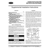
50VQP units with the SAV or duct pressure control option have supply fan VFDs that are factory installed, wired, and configured for the selected control method (SAV or duct pressure control). The VFD is installed in the blower section of the unit and can be accessed through the blower access panel (see Fig. 1). This guide provides information that can be useful for adjusting or servicing the supply fan VFD.
Fig. 1 VFD Location, 50VQP Units
50HQP units with the SAV or duct pressure control option have supply fan VFDs that are factory provided, but require field instal- lation and configuration. This guide provides information on installing, wiring, and config- uring the VFD. This information can be used in the case of a field VFD replacement or if configuration adjustment is necessary.
WARNING
Before performing service or maintenance operations on unit, turn off main power switch to unit. Electrical shock could cause personal injury.
WARNING
Improper installation, adjustment, alteration, service, or main- tenance can cause injury or property damage. Refer to this manual. For assistance or additional information, consult a qualified installer, service agency, or the gas supplier.
IMPORTANT: Carrier 50VQP and 50HQP constant vol- ume models (without SAV or duct pressure control) use motors that are not VFD rated and are not compatible with VFDs. Only Carrier models ordered with the VFD duct pressure control or Staged Air Volume (SAV) options use VFD rated motors and are VFD compatible.
FRONT OF UNIT
ELECTRICAL CONTROL BOX
VFD
BLOWER MOTOR
BLOWER MOTOR
BLOWER BLOWER
COMPRESSOR COMPRESSOR
Variable Frequency Drive (VFD) for 50HQP072-242, 50VQP072-360
Water Source Heat Pumps (WSHP)
2
VFD SHIPPING STORAGE LOCATION (50HQP UNITS ONLY)
The VFD is shipped internally inside the compressor access sec- tion of the unit. The VFD is located in a cardboard box along with the manufacturers installation manual. See Fig. 2. Inspect for shipping damage before proceeding with the VFD installation.
INSTALLING THE VFD (50HQP UNITS ONLY) NOTE: Installation must adhere to local codes and requirements. 1. Remove the VFD from the unit shipping storage location
(see Fig. 2). 2. Remove the VFD from the cardboard shipping box and
locate the ABB ACH550 VFD Installation, Operation, and Maintenance Manual.
3. Follow the instructions for VFD installation in the ABB ACH550 manual.
VFD INPUT AND OUTPUT POWER WIRING AND CONNECTIONS (50HQP UNITS ONLY)
NOTE: All remote VFD field wiring must be installed per local codes and requirements. 1. Disconnect unit power and remove the electrical control
box and compressor access panel. See Fig. 3. 2. Make field wiring connections between VFD input termi-
nals (U1, V1, and W1) and Terminal Block 3 (TB3) located in the electrical control box. See Fig. 4.
3. Make field wiring connections between VFD output termi- nals (U2, V2, and W2) and Terminal Block 4 (TB4) located in the electrical control box. See Fig. 4.
Fig. 2 Remote VFD Shipping Location, 50HQP Units
Fig. 3 Electrical Control Box Location, 50HQP Units
AIR COIL
COMPRESSORS
ELECTRICAL CONTROL BOX
VFD BOX
BLOWER BLOWER
BLOWER MOTOR
BLOWER MOTOR
ELECTRICAL CONNECTIONS
CONDENSATE DRAIN
ELECTRICAL BOX
CONTROLS, COMPRESSORS ACCESS
COMPRESSORS, REFRIGERATION COMPONENTS ACCESS
3
Fig. 4 VFD Input and Output Power Connections, 50HQP Units
4
DUCT PRESSURE VFD CONTROL AND LOW VOLTAGE CONNECTIONS
(50HQP UNITS ONLY) NOTE: All remote VFD field wiring must be installed per local codes and requirements. 1. Disconnect unit power and remove the electrical control
box and compressor access panel. See Fig. 3. 2. Make field wiring connections between VFD control ter-
minals AI1 (terminal #2), AGND (terminal #3) and 24V (terminal #10) and the remote Duct Static Sensor (DSS) located in the supply airflow ductwork. See Fig. 5.
3. Make field wiring connections between VFD control ter- minals 24V (terminal #10), DI1 (terminal #13), DI3 (ter- minal #15) and Terminal Block 5 (TB5) located in the electrical control box. See Fig. 5.
See Fig. 6 and 7 for typical wiring diagrams, VFD for Duct Static Pressure Control.
Fig. 5 Duct Pressure VFD Control and Low Voltage Connections, 50HQP Units
5
Fig. 6 VFD for Duct Static Pressure Control - Complete C Package
6
Fig. 7 VFD for Duct Static Pressure Control - Deluxe D Package
7
DUCT PRESSURE VFD PROGRAMMING PARAMETERS (ALL UNITS)
In duct pressure control mode, the supply fan will operate to main- tain a fixed static pressure set point (point 4011) as read by the duct static pressure sensor (DSS). Table 1 lists the factory default duct static pressure control VFD programming parameters, which require field configuration and adjustment based on the application requirements.
Table 1 Duct Pressure VFD Programming Parameters
GROUP NUMBER PARAMETER NUMBER DESCRIPTION VALUE 98 9802 Communication Protocol Selector NS Factory Default*
99
9902 Application Macro HVAC Default 9904 Motor control Mode Scalar 9905 Motor Nominal Voltage Refer to Motor Nameplate
9906 Motor Nominal Current Refer to Motor Nameplate
9907 Motor Nominal Frequency Refer to Motor Nameplate
9908 Motor Nominal Speed Refer to Motor Nameplate
9909 Motor Nominal Power Refer to Motor Nameplate
10 1001 EXT1 Commands DI1 Start/Stop 1002 EXT2 Commands COMM 1003 Direction Forward
11
1103 REF1 Select AI-1 1104 REF1 Minimum 0Hz at 60Hz/ 0Hz at 50Hz 1105 REF 1 Maximum 60 Hz at 60Hz / 50 Hz at 50Hz 1106 REF2 Select PID1OUT
12 1201 Constant Speed Select NOT SEL 1202 Constant Speed 1 60Hz
13
1301 Minimum AI-1 0% 1302 Maximum AI-1 100% 1303 Filter AI-1 1 Sec 1304 Minimum AI-2 20% 1305 Maximum AI-2 100% 1306 Filter AI-2 1 Sec
14 1401 Relay Output 1 Ready 1402 Relay Output 2 Run 1403 Relay Output 3 Fault (Inverted)
16 1601 Run Enable DI-1 1608 Start Enable 1 DI-4 1609 Start Enable 2 N/A
20
2002 Minimum Fan Speed 0 rpm 2003 Maximum Current 1800 rpm 2007 Minimum Frequency 0Hz 2008 Maximum Frequency 60Hz
21 2101 Start Function 3 (SCALAR FLYST) 2102 Stop Function Coast
22 2202 Accelerate Time 30 Seconds 2203 Decelerate Time 30 Seconds
26 2605 Volt/ Freq Ratio Square 2606 Switching Frequency 4Khz 2607 Switching Frequency Control ON
30
3006 Motor Thermal Time 1050s 3007 Motor Load Curve 100% 3008 Zero Speed Load 70% 3009 Break Point Frequency 35Hz 3010 Stall Function NOT SEL 3011 Stall Frequency 20 Hz 3012 Stall Time 20 Sec 3017 Earth Fault Enabled
8
* Change to BACnet if drive integration is required. Refer to motor name plate. ** To be adjusted in the field according to the static pressure requirements.
31
3101 Number of Retries 5 3102 Trial Time 30 Sec 3103 Delay Time 6 Sec 3104 AR Overcurrent Enabled 3105 AR Overvoltage Enabled 3106 AR Under voltage Enabled 3107 AR AI
34
3401 Signal Parameter 1 Output Freq 3402 Signal 1 Minimum 0
3403 Signal 1 Maximum 60/ 50 ( Maximum motor operating Hertz)
3404 Output 1 DPS Form 0 3405 Output 1 DSP Unit % SP 3406 Output 1 Minimum 0 3407 Output 1 Maximum 100
3408 Signal Parameter 2 Current ( Motor Current Measure by the Drive)
3409 Signal 2 Minimum 0 3410 Signal 2 Maximum FLA + 15% A 3411 Output 2 DPS Form 0 3412 Output DSP Unit A (2) 3413 Output 2 Minimum 0 3414 Output 2 Maximum FLA + 15% A 3415 Signal Parameter 3 AI-1 3416 Signal 3 Minimum 0 3417 Signal 3 Maximum 10 3418 Output 3 DPS Form 0 3419 Output DSP Unit V (2) 3420 Output 3 Minimum 0 3421 Output 3 Maximum 10
40
4001 Gain 2.5 4002 Integration Time 3 Sec 4005 Error Value Inver NO 4006 Units INWC ( Inches of water column) 4007 Display Format x.xxx 4009 100% Value 0.5 4010 Setpoint Select Internal 4011 Internal Setpoint 0.25** 4012 Setpoint Minimum 0V 4013 Sepoint Maximum 10V 4027 PID1 Parameter Set SET1
Table 1 Duct Pressure VFD Programming Parameters(cont)
GROUP NUMBER PARAMETER NUMBER DESCRIPTION VALUE
9
STAGED AIR VOLUME (SAV) VFD CONTROL AND LOW VOLTAGE CONNECTIONS
(50HQP UNITS ONLY) NOTE: All remote VFD field wiring must be installed per local codes and requirements. 1. Disconnect unit power and remove the electrical control
box and compressor access panel. See Fig. 3. 2. Make field wiring connections between VFD control ter-
minals 24V (terminal #10), DI1 (terminal #13), DI2 (ter- minal #14), DI3 (terminal #15) and Terminal Block 5 (TB5) located in the electrical control box. See Fig. 8.
See Fig. 9-11 for typical wiring diagrams.
Fig. 8 SAV VFD Control and Low Voltage Connections, 50HQP Units
10
Fig. 9 VFD for 2-Speed Fan Control - Complete C Package
11
Fig. 10 VFD for 2-Speed Fan Control - Deluxe D Package
12
Fig. 11 VFD for 2-Speed Fan Control with WSHP Open
13
Fig. 11 VFD for 2-Speed Fan Control with WSHP Open (cont)
1
UNIT TERMINAL BLOCK (TB1) CLASS II VOLTAGE
STANDARD COMPONENTS:
DATS - DISCHARGE AIR TEMP SENSOR LWTS - LEAVING WATER TEMP SENSOR
OPTIONAL WIRING
J1-9 USED TO CONNECT FIRE ALARM RELAY OR PHASE MONITOR OPTIONS
1
2
2 FACTORY JUMPER IS INSTALLED ON J5-5 AND J5-6 IF CONDENSATE FLOAT SWITCH (NC) IS NOT PRESENT
3
3 FOR 2-STAGE UNITS, CONNECT CMR CONN ACROSS PINS 4 AND 6 OF CMR1 WITH SIGNAL CMR-4 GOING TO PIN 4 AND SIGNAL CMR-2 GOING TO PIN 6.
4
4 ELECTRIC HEAT (W1) OR ECONOMIZER (E). BOTH OPTIONS WILL NOT BE PRESENT IN THE SAME UNIT
14
SAV VFD PROGRAMMING PARAMETERS (ALL UNITS)
In SAV control mode, the supply fan will operate based on the call for cooling or heating. When there is a call for fan only or stage 1 cooling, the supply fan will operate at 40 Hz (parameter 1206). When there is a call for second stage cooling or any heating call, the supply fan will operate at 60 Hz (parameter 1202). Table 2 lists the factory default SAV VFD programming parameters, which re- quire field configuration.
Table 2 SAV VFD Programming Parameters
GROUP NUMBER PARAMETER NUMBER DESCRIPTION VALUE 98 9802 Communication Protocol Selector NS Factory Default*
99
9902 Application Macro HVAC Default 9904 Motor control Mode Scalar 9905 Motor Nominal Voltage Refer to Motor Nameplate
9906 Motor Nominal Current Refer to Motor Nameplate
9907 Motor Nominal Frequency Refer to Motor Nameplate
9908 Motor Nominal Speed Refer to Motor Nameplate
9909 Motor Nominal Power Refer to Motor Nameplate
10 1001 EXT1 Commands DI1 - Start/Stop 1002 EXT2 Commands COMM 1003 Direction Forward
11
1103 REF1 Select AI-1 1104 REF1 Minimum 0Hz at 60Hz/ 0Hz at 50Hz 1105 REF 1 Maximum 60 Hz at 60Hz / 50 Hz at 50Hz 1106 REF2 Select PID1OUT
12
1201 Constant Speed Select DI1, DI2, DI3 1202 Constant Speed 1 60Hz 1203 Constant Speed 2 0Hz 1204 Constant Speed 3 60Hz 1205 Constant Speed 4 0Hz 1206 Constant Speed 5 40Hz 1207 Constant Speed 6 0Hz 1208 Constant Speed 7 60Hz
13
1301 Minimum AI-1 0% 1302 Maximum AI-1 100% 1303 Filter AI-1 1 Sec 1304 Minimum AI-2 20% 1305 Maximum AI-2 100% 1306 Filter AI-2 1 Sec
14 1401 Relay Output 1 Ready 1402 Relay Output 2 Run 1403 Relay Output 3 Fault (Inverted)
16 1601 Run Enable DI-1 1608 Start Enable 1 DI-4 1609 Start Enable 2 N/A
20
2002 Minimum Fan Speed 0 rpm 2003 Maximum Current 1800 rpm 2007 Minimum Frequency 0Hz 2008 Maximum Frequency 60Hz
21 2101 Start Function 3 (SCALAR FLYST) 2102 Stop Function Coast
22 2202 Accelerate Time 30 Seconds 2203 Decelerate Time 30 Seconds
26 2605 Volt/Freq Ratio Square 2606 Switching Frequency 4Khz 2607 Switching Frequency Control ON
15
* Change to BACnet if drive integration is required. Refer to motor name plate. ** To be adjusted in the field according to the static pressure requirements.
30
3006 Motor Thermal Time 1050s 3007 Motor Load Curve 100% 3008 Zero Speed Load 70% 3009 Break Point Frequency 35Hz 3010 Stall Function NOT SEL 3011 Stall Frequency 20 Hz 3012 Stall Time 20 Sec 3017 Earth Fault Enabled
31
3101 Number of Retries 5 3102 Trial Time 30 Sec 3103 Delay Time 6 Sec 3104 AR Overcurrent Enabled 3105 AR Overvoltage Enabled 3106 AR Under voltage Enabled 3107 AR AI
34
3401 Signal Parameter 1 Output Freq 3402 Signal 1 Minimum 0 3403 Signal 1 Maximum 60/ 50 ( Maximum motor operating Hertz) 3404 Output 1 DPS Form 0 3405 Output 1 DSP Unit % SP 3406 Output 1 Minimum 0 3407 Output 1 Maximum 100
3408 Signal Parameter 2 Current ( Motor Current Measure by the Drive)
3409 Signal 2 Minimum 0 3410 Signal 2 Maximum FLA + 15% A 3411 Output 2 DPS Form 0 3412 Output DSP Unit A (2) 3413 Output 2 Minimum 0 3414 Output 2 Maximum FLA + 15% A 3415 Signal Parameter 3 AI-1 3416 Signal 3 Minimum 0 3417 Signal 3 Maximum 10 3418 Output 3 DPS Form 0 3419 Output DSP Unit V (2) 3420 Output 3 Minimum 0 3421 Output 3 Maximum 10
40
4001 Gain 2.5 4002 Integration Time 3 Sec 4005 Error Value Inver NO 4006 Units INWC ( Inches of water column) 4007 Display Format x.xxx 4009 100% Value 0.5 4010 Setpoint Select Internal 4011 Internal Setpoint 0.25** 4012 Setpoint Minimum 0V 4013 Sepoint Maximum 10V 4027 PID1 Parameter Set SET1
Table 2 SAV VFD Programming Parameters (cont)
GROUP NUMBER PARAMETER NUMBER DESCRIPTION VALUE
Manufacturer reserves the right to discontinue, or change at any time, specifications or designs without notice