Manufacturer reserves the right to discontinue, or change at any time, specifications or designs without notice and without incurring obligations. Catalog No. 533-00077 Printed in U.S.A. Form 30-1SI Pg 1 1-07 Replaces: 30GTN-4SIBook 2
Tab 5c
Installation Instructions Part Number 30GT-911---063
CONTENTS SAFETY CONSIDERATIONS . . . . . . . . . . . . . . . . . . . . . . 1 INSTALLATION . . . . . . . . . . . . . . . . . . . . . . . . . . . . . . . . . 1-6
SAFETY CONSIDERATIONS
Installation of this accessory can be hazardous due to sys- tem pressures, electrical components, and equipment location (such as a roof or elevated structure).
Only trained, qualified installers and service technicians should install, start up, and service this equipment.
When installing this accessory, observe precautions in the literature, on labels attached to the equipment, and any other safety precautions that apply. Follow all safety codes. Wear safety glasses and work gloves. Use care in handling and installing this accessory
INSTALLATION The service port is intended to allow remote connection of
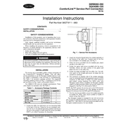
the ComfortLinkTM Navigator display. This will allow service technicians to use the Navigator module right at or near the chillers compressors when servicing or troubleshooting. See Table 1 for accessory package contents. The suggested mounting position is shown in Fig. 1. Locations for the service port are shown in Fig. 2 and 3, referenced in Table 2.
The 30RB315-390 units are modular combinations. These units require two accessory kits. See Table 3.
Table 1 Accessory Package Contents
1. Locate the utility box and knock out two mounting holes in the back of the box. Using the box as a template, posi- tion the box in the desired mounting position and secure the box to the upright or baffle using the screws provided. Drill 3/16-in. holes if necessary for mounting.
2. Attach the forked terminal end of the conduit assembly to the bottom of the utility box. Connect each of the five fork terminals to the modular jack. See Fig. 4.
3. Using the screws provided with the modular jack, attach the jack to the utility box.
4. Locate the gasket and screws provided with the cover. Carefully remove the inner portion of the gasket and attach the cover to the utility box.
5. Locate the plugs provided with the utility box. Use sili- cone caulk on the threads and secure the plugs into the unused box openings.
6. The connector at opposite end of the conduit assembly must be connected to the local equipment network (LEN) connector on TB3. Refer to Table 4 for LEN connector and conduit routing locations. For 30XA units with Navigator option factory installed, the Navigator module needs to be disconnected to allow service port cable to be plugged in. See Fig. 5-8, referenced in Table 4.
NOTE: Do NOT connect the service port to the CCN (Carrier Comfort Network) connector, as it may damage the device. Figures 5-8 reference both the LEN and CCN connectors.
7. Use the wire ties provided to secure the conduit assembly as needed. For 30XA units, secure conduit to bundle of sensor wiring. See Table 4.
The Navigator module is intended for use with the service port. It must be ordered separately, Carrier accessory part num- ber 30GT-911---062. Refer to the instructions provided with the Navigator module accessory for more details.
To avoid the possibility of electrical shock, open and tag all disconnects before installing this equipment. Be aware that there may be more than one disconnect. Serious personal injury may result.
ITEM PART NO. QUANTITY Utility Box HX30FZ012 1 Cover HX28ZZ001 1 Conduit Assembly 30GT415675 1 Modular Jack HK50AA040 1 Screws, 1/4 in. diameter by 5/8 in. Long AL38AM307 2
Wire Ties HY76TB125 12
30RB060-390 30XA080-120
ComfortLink Service Port Connection 60 Hz
Fig. 1 Service Port Accessory
a30-4529
 en
en