Carrier 30XV140-500 v9 Installation Instructions
![Carrier 30XV140-500 manual cover](/images/f02134106e92bebbdab668cc/thumbs/thumb175x175.webp)
![English English](/static/img/blank.webp)
Manufacturer reserves the right to discontinue, or change at any time, specifications or designs without notice and without incurring obligations. Catalog No. 04-53300217-01 Printed in U.S.A. Form 30XV-16SI Pg 1 7-19 Replaces: 30XV-12SI
Installation Instructions Part No. 30XV70001701 (BACnet/Modbus)
Part No. 30XV70001901 (LonWorks) SAFETY CONSIDERATIONS . . . . . . . . . . . . . . . . . . . 1 INTRODUCTION . . . . . . . . . . . . . . . . . . . . . . . . . . . . . . 1 INSTALLATION . . . . . . . . . . . . . . . . . . . . . . . . . . . . . . 3 Preliminary Steps . . . . . . . . . . . . . . . . . . . . . . . . . . . . 3 BACnet/Modbus Translator . . . . . . . . . . . . . . . . . . . . 3 LonWorks Translator . . . . . . . . . . . . . . . . . . . . . . . . . 4
SAFETY CONSIDERATIONS Installation of this accessory can be hazardous due to electrical components and equipment location (such as a roof or elevated structure). Only trained, qualified installers and service technicians should in- stall and service this equipment. When installing this accessory, observe precautions in the litera- ture and on labels attached to the equipment, as well as other safe- ty precautions that may apply. Follow all safety codes. Wear safety glasses and work gloves. Use care when handling and installing this accessory. Follow proper Lockout/Tagout procedures.
INTRODUCTION The Carrier CCN BACnet/Modbus Translator Accessory module with RS-485 communication, shown in Fig. 1, is a micro-controller-based module that provides the ability to easily interface Carrier CCN controllers to third party non- Carrier control equipment. The BACnet/Modbus Carrier Translator provides CCN to Modbus Remote Terminal Unit (RTU) and BACnet Master-Slave Twisted-Pair (MS/TP) protocol conversion. See Table 1 for the contents of the Carrier CCN BACnet/Modbus Translator accessory package. The LonWorks Carrier Translator Accessory module with LON FT-10A communication, shown in Fig. 2, is a micro-controller- based module that provides the ability to easily interface Carrier CCN controllers to third party non-Carrier control equipment. The LonWorks Carrier Translator provides CCN to LonWorks FT-10A ANSI/EIA-709.1 protocol conversion. See Table 2 for the contents of the Carrier CCN LonWorks Translator accessory package. The 30XV units accept one Carrier CCN BACnet/Modbus or LonWorks Translator accessory. The accessory kit provides all necessary wires and hardware for accessory installation.
WARNING
Electrical shock can cause personal injury and death. Shut off all power to this equipment during installation. There may be more than one disconnect switch. Tag all disconnect locations to alert others not to restore power until work is completed.
Table 1 Accessory Package Contents (30XV70001701)
ITEM # ITEM UNIT USAGE P/N QTY 1 BACnet/Modbus Translator Module All 30XV50122401 1 2 SCREW All AC41AA086 4 3 SCREW All AL56AU128 4 4 WIRE TIE All HY76TB110 4 5 BRACKET 350-500 (30XVA/XVB) 30XV50103201 1
6 HARNESS ASSY 140-325 (30XVA), 350-500 (30XVA/XVB) 30XV50103101 (30XVHLAACL-A00) 1
7 HARNESS ASSY 140-325 (30XVB) 30XV50119801 (30XVHVAAFL-A00) 1 8 INSTRUCTIONS All 30XV-16SI 1
30XV140-500 BACnet*/Modbus and LonWorks**
Translator Accessories
* BACnet is a registered trademark of ASHRAE (American Society of Heating, Refrigerating and Air-conditioning Engineers).
Modbus is a registered trademark of Schneider Electric. ** LonWorks is a registered trademark of Echelon Corporation.
2
Fig. 1 BACnet/Modbus Translator Module
Fig. 2 LonWorks Translator Module
Table 2 Accessory Package Contents (30XV70001901)
ITEM # ITEM UNIT USAGE P/N QTY 1 LON Translator Module All 30XV50122501 1 2 SCREW All AC41AA086 4 3 SCREW All AL56AU128 4 4 WIRE TIE All HY76TB110 4 5 BRACKET 350-500 (30XVA/XVB) 30XV50103201 1
6 HARNESS ASSY 140-325 (30XVA), 350-500 (30XVA/XVB) 30XV50103101 (30XVHLAACL-A00) 1
7 HARNESS ASSY 140-325 (30XVB) 30XV50119801 (30XVHVAAFL-A00) 1 8 INSTRUCTIONS All 30XV-16SI 1
3
INSTALLATION
Preliminary Steps Follow these steps for either the BACnet/Modbus or LonWorks Translator: 1. Inspect package contents for missing or damaged parts. File a
claim with the shipping agency if parts are damaged, and notify your Carrier representative if any item is missing.
2. Open and tag all electrical disconnects in accordance with proper Lockout/Tagout procedures.
3. Open the unit control box door.
4. Install the CCN Carrier Translator module in the location shown in Fig. 3, 4 or 5 by using screws (item #2). For unit sizes 350-500 tons (Fig. 5) a bracket (item #5) must be installed first using screws (item #3) and then mounting CCN Carrier Translator module to the bracket.
5. Proceed to the steps outlined in the BACnet/Modbus Trans- lator section on this page or the LonWorks Translator sec- tion on page 4 as appropriate.
Fig. 3 Translator Module Installation Location for 30XVA140-325
Fig. 4 Translator Module Installation Location for 30XVB140-325
Fig. 5 Translator Module Installation Location for 30XV350-500
BACnet/Modbus Translator 1. Complete the procedure outlined in the previous Preliminary
Steps section. 2. Referring to Fig. 6, for 30XVB 140-325 locate wire har-
ness (P/N 3050119801, item #7), for 30XVA 140-325 and 30XVA/XVB 350-500 locate wire harness (P/N 30XV50103101, item #6) in the accessory kit.
3. Connect the red wire labeled TB4-3 to an open connection point on terminal block TB4-3.
4. Connect the other end of the red wire labeled LON/BAC J1- 24VAC to the J1-1 terminal on the BACnet/Modbus Transla- tor board.
5. Connect the brown wire labeled TB11-X2 to an open connec- tion point on terminal block TB11-X2.
6. Connect the other end of the brown wire labeled LON/BAC J1-GND to the J1-2 terminal on the BACnet/Modbus Trans- lator board.
7. Referring to Fig. 6, connect black wire labeled LON/BAC J2 to the terminal marked J2 on the BACnet/Modbus Translator board.
8. Connect the white wire labeled LON/BAC J2 G to the termi- nal marked J2 G on the BACnet/Modbus Translator board.
9. Connect red wire labeled LON/BAC J2+ to the terminal marked J2+ on the BACnet/Modbus Translator board.
10. Connect the other end of the cable which has a 3-position plug and is labeled TB3 into the CCN connection on TB3 located as shown in Fig. 3 for 30XVA 140-325, Fig. 4 for 30XVB 140-325 and Fig. 5 for 30XVA/XVB 350-500.
11. Ensure that electrical connections are tight, and restore power to the unit.
12. With power restored to the unit, the BACnet/Modbus Trans- lator board has three LEDs that are used to indicate opera- tional status. Refer to Table 3 for a description of each LED and what it indicates. For specific setup/configuration and table of points refer to the 30XV Start-up and Troubleshoot- ing guides.
13. Remove tags from disconnects and close the control box door.
TB3
TRANSLATOR CARD
TB4
TB11
TB3
TRANSLATOR CARD
TB4
TB11
TB3
TRANSLATOR CARD
TB4
TB11
Manufacturer reserves the right to discontinue, or change at any time, specifications or designs without notice and without incurring obligations. Catalog No. 04-53300217-01 Printed in U.S.A. Form 30XV-16SI Pg 4 7-19 Replaces: 30XV-12SI
Carrier Corporation 2018
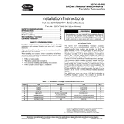
Fig. 6 BACnet/Modbus Translator Module Wiring Diagram
LonWorks Translator 1. Complete the procedure outlined in the Preliminary Steps
section on page 3. 2. Referring to Fig. 7, 30XVB 140-325 locate wire harness
(P/N 3050119801, item #7) or for 30XVA 140-325 and 30XVA/XVB 350-500 locate wire harness (P/N 30XV50103101, item #6) in the accessory kit.
3. Connect the red wire labeled TB4-3 to an open connection point on terminal block TB4-3.
4. Connect the other end of the red wire labeled LON/BAC J1- 24VAC to the J1-1 terminal on the LonWorks Translator board.
5. Connect the brown wire labeled TB11-X2 to an open connec- tion point on terminal block TB11-X2.
6. Connect the other end of the brown wire labeled LON/BAC J1-GND to the J1-2 terminal on the LonWorks Translator board.
7. Referring to Fig. 7, connect black wire labeled LON/BAC J2 to the terminal marked J2 on the LonWorks Translator board.
8. Connect the white wire labeled LON/BAC J2 G to the termi- nal marked J2 G on the LonWorks Translator board.
9. Connect red wire labeled LON/BAC J2+ to the terminal marked J2+ on the LonWorks Translator board.
10. Connect the other end of the cable which has a 3-position plug and is labeled TB3 into the CCN connection on TB3 located as shown in Fig. 3 for 30XVA 140-325, Fig. 4 for 30XVB 140-325 and Fig. 5 for 30XVA/XVB 350-500.
11. Ensure that electrical connections are tight, and restore power to the unit.
12. With power restored to the unit, the LonWorks Translator board has three LEDs that are used to indicate operational sta- tus. Refer to Table 4 for a description of each LED and what it indicates. For specific setup/configuration and table of points refer to the 30XV Start-up and Troubleshooting guides.
13. Remove tags from disconnects and close the control box door.
The LonWorks Carrier Translators default CCN address is 0,200 (bus number, system element number). The default CCN baud rate is 9600 bps. Each LonWorks Carrier Translator has a unique LON address. The LON address can be sent to LON configuration tools when the LON Service Pin is pressed. See Fig. 2 for location of the LON Service Pin.
Fig. 7 LonWorks Translator Module Wiring Diagram
Wire to third party Modbus or BACnet MS/TP communication network
TB3
30XV50103101
Wire to third party LonWorks MS/TP communication network
TB3
30XV50122501
Table 3 BACnet/Modbus Translator LED Indicators
LED COLOR INDICATES
Status Red Operating, initialization and configuration status. The LED blinks at a 2 Hz rate when initializing and at 1 Hz when operating correctly.
CCN Yellow The Carrier Translator is sending CCN communication messages to the connected CCN controller. If the connected CCN controller is responding, its CCN LED will blink when a message is sent back to the Carrier Translator.
RS-485 Green The Carrier Translator is sending RS-485 communication messages to the Modbus or BACnet MS/TP network.
Table 4 LonWorks Translator LED Indicators
LED COLOR INDICATES
Status Red Operating, initialization and configuration status. The LED blin