Carrier 30XA080-501 v2 Installation Instructions
Manufacturer reserves the right to discontinue, or change at any time, specifications or designs without notice and without incurring obligations. Catalog No. 04-53300120-01 Printed in U.S.A. Form 30-23SI Pg 1 1-2021 Replaces: 30-15SI
Installation Instructions Part Numbers: 00EFN900000400A, 00EFN900000500A, 00EFN900000600A,
00EFN900000700A, 00EFN900001800A, 00EFN900001900A NOTE: These instructions apply to 30RB060-390 units with starting serial number 3107Q. To install this accessory on 30RB060-390 units with serial numbers prior to 3107Q refer to Installation Instructions form number 30-8SI. This accessory is not applicable to 30XA variable speed chillers with Greenspeed intelligence or 30RB units with Greenspeed intelligence. Units with Greenspeed intelligence operate all condenser fans with a Variable Frequency Drive.
CONTENTS Page
SAFETY CONSIDERATIONS . . . . . . . . . . . . . . . . . . . 1 GENERAL . . . . . . . . . . . . . . . . . . . . . . . . . . . . . . . . . . . 1 INSPECT SHIPMENT . . . . . . . . . . . . . . . . . . . . . . . . . . 2 INSTALLATION . . . . . . . . . . . . . . . . . . . . . . . . . . . . . . 4 Step 1 Install Field-Fabricated Wind Baffles . . . . 4 Step 2 Wire the Control Panel . . . . . . . . . . . . . . . . 5 Step 3 Mount the Low Ambient Temperature
Head Pressure Control . . . . . . . . . . . . . . . . . . . . . 11 Step 4 Configure for Low Ambient Temperature
Head Pressure Control Operation . . . . . . . . . . . . 17 Step 5 Configure Low Ambient Temperature
Head Pressure Control . . . . . . . . . . . . . . . . . . . . . 20 Step 6 Test the Low Ambient Temperature
Head Pressure Control . . . . . . . . . . . . . . . . . . . . . 23
SAFETY CONSIDERATIONS Installation and servicing of air-conditioning equipment can be hazardous due to system pressure and electrical components. Only trained and qualified service personnel should install, repair, or service air-conditioning equipment. Untrained personnel can perform basic maintenance functions of cleaning coils and filters and replacing filters. All other operations should be performed by trained service personnel. When working on air-conditioning equipment, observe precautions in the literature, tags and labels attached to the unit, and other safety precautions that may apply. Follow all safety codes. Wear safety glasses and work gloves. Use quenching cloth for unbrazing operations. Have fire extinguisher available for all brazing operations. It is important to recognize safety information. This is the safety- alert symbol . When you see this symbol on the unit and in instructions or manuals, be alert to the potential for personal injury. Understand the signal words DANGER, WARNING, CAUTION, and NOTE. These words are used with the safety-alert symbol. DANGER identifies the most serious hazards which will result in severe personal injury or death. WARNING signifies hazards which could result in personal injury or death. CAUTION is used to identify unsafe practices, which may result in minor personal injury or product and property damage. NOTE is used to highlight suggestions which will result in enhanced installation, reliability, or operation.
GENERAL This book contains instructions for the installation of the low am- bient temperature head pressure control accessory kit for 30RB060-390 and 30XA080-501 units. NOTE: Unit sizes 30RB315-390 are modular units that are shipped in separate sections as modules A or B as noted in posi- tion 8 of the unit model nameplate. The nameplate for modular units contains only the first two digits of the unit size. For exam- ple, 30RB size 315 nameplates read 30RB*31A.... and 30RB*31B, where * is a wild card indicating the design series. See Table 1 for a listing of unit sizes and modular combinations.
Table 1 Modular Combinations
NOTE: An * in the 5th position of the model number indicates the design series.
The low ambient temperature control utilizes a variable frequency drive (VFD) to control condenser fan speed based on saturated condensing temperature. The control can only be used with mo- tors rated for use with VFDs. Each circuits discharge pressure is used by the ComfortLink controls to determine the output to the VFD. The fan board(s) provide a 0 to 10 vdc output to each drive for fan speed control. All VFDs are microprocessor-controlled and use insulated gate bi- polar transistor (IGBT) technology. The pulse width modulation scheme used by the control allows for quiet motor operation. The control will vary the motor speed signal to the VFD to maintain the saturated condensing temperature (SCT) at the calculated head pressure set point. If the SCT is greater than the set point, the fan signal will increase to increase fan speed. If SCT is less than the set point, the fan signal will decrease to slow the fan speed. At higher SCTs, the fan will go to full speed and remain there since it cannot go fast enough to bring the pressure down to the set point.
WARNING
Electrical shock can cause personal injury and death. Shut off all power to this equipment during installation. There may be more than one disconnect switch. Tag all disconnect locations to alert others not to restore power until work is completed.
MODULE UNITS MODULE A MODULE B 30RB*315 30RB*160 30RB*160 30RB*330 30RB*170 30RB*160 30RB*345 30RB*170 30RB*170 30RB*360 30RB*190 30RB*170 30RB*390 30RB*190 30RB*190
30RB060-390 30XA080-501
Low Ambient Temperature Head Pressure Control Accessory
2
When the saturated condensing temperature drops, a fan running at full speed may draw too much air across the condenser coil to maintain a minimum saturated condensing temperature. During these conditions, the VFD will begin to slow down and begin to maintain a saturated condensing temperature set point. NOTE: The VFD is phase insensitive in regard to incoming line voltage, which means that the VFD will operate with any phase sequence of the incoming three-phase power. The standard outdoor air temperature limitation of 30RB and 30XA chillers is 32F (0C). The low ambient temperature con- troller operation kit can be used to extend unit operation down to 20F (29C).
NOTE: Wind baffles are required if wind velocity is anticipated to be greater than 5 mph (8 km/h).
INSPECT SHIPMENT Inspect the contents of the accessory package before installing. File a claim with the shipping company if there is shipping dam- age. Contact your local Carrier representative if any parts are missing. See Table 2 for accessory content usage. See Table 3 for accessory package contents.
Table 2 Low Ambient Temperature Head Pressure Control Package Usage
* Not applicable for 30RB with Greenspeed intelligence or 30XA with Greenspeed intelligence.
Refer to unit nameplate for voltage designation.
UNIT SIZE* VOLTAGE (3 ph, 60 Hz)
NUMBER OF CIRCUITS PACKAGE NO.
NUMBER OF ACCESSORY
KITS REQUIRED
30RB
060, 070, 080
208/230 2 00EFN900000600A 1 380 2 00EFN900000400A 1 460 2 00EFN900000400A 1 575 2 00EFN900001800A 1
090,100,110,120, 130,150,160,170,190
208/230 2 00EFN900000700A 2 380 2 00EFN900000500A 2 460 2 00EFN900000500A 2 575 2 00EFN900001900A 2
210,225,250,275,300
208/230 3 00EFN900000700A 3 380 3 00EFN900000500A 3 460 3 00EFN900000500A 3 575 3 00EFN900001900A 3
315,330,345,360,390
208/230 4 00EFN900000700A 4 380 4 00EFN900000500A 4 460 4 00EFN900000500A 4 575 4 00EFN900001900A 4
30XA
080,082,090,092,100,102,110,112,120, 122,140,142,160,162,180,182,200,202, 220,222,240,242,260,262,280,282,300, 302,325,327,350,352,401,451,476,501
200 2 00EFN900000700A 2 230 2 00EFN900000700A 2 380 2 00EFN900000500A 2 460 2 00EFN900000500A 2 575 2 00EFN900001900A 2
400,450,500 380 3 00EFN900000500A 3 460 3 00EFN900000500A 3 575 3 00EFN900001900A 3
3
Table 3 Low Ambient Temperature Head Pressure Control Package Contents
LEGEND
* Includes the panel, drives, fuse block, fuses, drive filters, drive wire kit and operator display panel.
When ordering the Siemens VFD for 575-v unit replacement, note that the replace- ment drive does not include the VFD operator panel. The VFD operator panel must be ordered separately.
** Fan board shipped in accessory kit is supplied to replace fan board 1 shipped with the unit (part number 32GB500432E). See page 11, item 10 for more information.
ITEM
LOW AMBIENT TEMPERATURE HEAD PRESSURE CONTROL PACKAGE NUMBER
00EFN900000400A (380 V, 460 V UNITS)
00EFN900000500A (380 V, 460 V UNITS)
00EFN900000600A (200, 208/230 V
UNITS)
00EFN900000700A (200, 208, 230 V
UNITS)
00EFN900001800A (575 V UNITS)
00EFN900001900A (575 V UNITS)
Item Description (Qty) DUAL VFD PANEL ACCESSORY (INCLUDES 2 VFDS)
SF700091* (1) SF700081*
(1) SF700101* (1)
SINGLE VFD PANEL ACCESSORY SF700401*
(1) SF700400* (1) SF700402*
(1)
FAN MOTOR POWER CABLES (ATTACHED TO VFD)
(2) (1) (2) (1) (2) (1)
FUSE BLOCK CHCC3 (2) CHCC3 (1) CHCC3 (2) CHCC3 (1) CHCC3 (2) CHCC3 (1)
FUSES, 30 AMP ATMR-30 (6) ATMR-30 (3) ATMR-30 (6) ATMR-30 (3) ATMR-30 (6) ATMR-30 (3)
VARIABLE FREQUENCY DRIVE HR46TN008 (2) HR46TN008 (1) HR46TN007 (2) HR46TN007 (1) 6SE64402UE240CA1 (2) 6SE64402UE240CA1 (1)
VFD OPERATOR DISPLAY PANEL NA NA NA NA 6SE64000BP000AAO
(2) 6SE64000BP000AAO
(1)
MOUNTING PLATE 00PSN500037100A (1)
00PSN500037100A (1)
00PSN500037100A (1)
00PSN500037100A (1)
00PSN500037100A (1)
00PSN500037100A (1)
SUPPORT PLATE 00PSN500034400A (1)
00PSN500034400A (1)
00PSN500034400A (1)
00PSN500034400A (1)
00PSN500034400A (1)
00PSN500034400A (1)
WIRING COVER 00PSN500036500A (1)
00PSN500036500A (1)
00PSN500036500A (1)
00PSN500036500A (1)
00PSN500036500A (1)
00PSN500036500A (1)
WIRING BUSHING HY93NH091 (1) HY93NH091 (1) HY93NH091 (2) HY93NH091 (1) HY93NH091 (2) HY93NH091 (1)
6MM SCREWS 00PPN500000302A (9)
00PPN500000302A (9)
00PPN500000302A (9)
00PPN500000302A (9)
00PPN500000302A (10)
00PPN500000302A (9)
8MM SCREWS 00PPN500000201A (10)
00PPN500000201A (9)
00PPN500000201A (10)
00PPN500000201A (9)
00PPN500000201A (9)
00PPN500000201A (9)
FAN BOARD 1 32GB500442E**
WIRE TIES Wire Ties (20)
AWG American Wire Gage VFD Variable Frequency Drive
4
INSTALLATION
Step 1 Install Field-Fabricated Wind Baffles
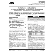
Field-fabricated and installed wind baffles are required if the wind velocity is anticipated to be greater than 5 mph (8 km/h) on units equipped with the low ambient temperature head pressure control accessory. If the application requires wind baffles, units require two different wind baffle designs, one for each end of the unit. Wind baffles should be constructed using a minimum 18-gage gal- vanized sheet metal or other suitable corrosion-resistant material with cross breaks for strength. Use field-supplied screws to attach baffles to the corner posts of the machine. Be sure to hem or turn a
flange on all edges to eliminate sharp edges on the baffles. See Fig. 1 for sizes and details of the baffles required. Mount the smaller height baffle on the control box end. It is recommended that the upper notches be used for mounting the baffles. This re- duces the risk of damaging the coil while drilling a mounting hole. Loosen the upper corner post bolts and slide the baffle under the bolt and washer. Tighten the bolt. Drill two holes at the bottom of the baffle through the flange and corner post. Mount baffles with field-supplied screws to secure the baffle to the frame. Repeat the process for the opposite end. See Fig. 2 for typical end views of the chillers with baffles installed.
WARNING
To avoid the possibility of electrical shock, open all discon- nects before installing or servicing this accessory.
CAUTION
To avoid damage to refrigerant coils and electrical compo- nents, use extreme care when drilling screw holes and screw- ing in fasteners.
Cross break these faces. Hem these 3 edges both top
and bottom.
See Detail A
1880 [74.0]
Detail A Typical Both Flanges
X
180 [7.0]
18 [0.75] 31 [1.25]
18 [0.75]
21 [0.88]
70 [2.75]
305 [12.0]
Fig. 1 Field-Fabricated and Field-Installed Wind Baffles
Material: 18 ga. Corrosion Resistant Sheet Metal. Dimensions are in mm [inches].
UNIT SIZE VOLTAGE POSITION BAFFLE HEIGHT (X)
30RB060-390 All Control/Power End 635 [25.0] Opposite Control Power End 1040 [41.0]
30XA080-120 All Control/Power End 635 [25.0] Opposite Control Power End 1040 [41.0]
30XA140-202 200,230
Control/Power End 635 [25.0] Opposite Control Power End 1040 [41.0]
380,460,575 Both Ends 1040 [41.0] 30XA220-501 All Both Ends 1040 [41.0]
5
Step 2 Wire the Control Panel For the appropriate fan motor, locate the fan contactor in the control panel. See Tables 4 and 5. See Fig. 3 and 4 for fan motor locations. NOTE: The C circuit fan contactors and fan board for 30RB210- 300 units are in the compressor side power box near the C circuit compressors and not in the fan/control box at the end of the unit. Fan wiring crosses the chiller in a conduit from the coil wiring tray to the back of the C circuit power box. NOTE: The C circuit fan contactors and fan board for 30XA400, 450, and 500 units are in the compressor side power box near the C circuit compressors.
Table 4 30RB060-390 Fan Motors Controlled by the VFD
(Units produced starting with serial number 3107Q)
Table 5 30XA080-501 Fan Motors Controlled by the VFD
Fig. 2 Wind Baffles Installed on Ends of 30RB Units
CONTROL/POWER END
OPPOSITE THE CONTROL BOX END
30RB UNIT SIZE CIRCUIT A MOTOR
CIRCUIT B MOTOR
CIRCUIT C MOTOR
060,070 FM1 FM4 080 FM1 FM3
090-100 FM1 FM5 110 FM1 FM5
120-150 FM3 FM7 160-170,315-345,360B FM5 FM9
190,360A,390 FM5 FM11 210, 225 FM3 FM7 FM11
250 FM3 FM7 FM13 275 FM5 FM11 FM15 300 FM5 FM11 FM17
30XA UNIT SIZE
CIRCUIT A MOTOR
CIRCUIT B MOTOR
CIRCUIT C MOTOR
080,082 FM5 FM1 090-122 FM7 FM1 140-162 FM9 FM1 180-202 FM11 FM1 220-242 FM13 FM1 260-302 FM15 FM1 325-352 FM17 FM1
400 FM11 FM1 FM19 401 FM19 FM1
450, 500 FM13 FM1 FM21 451, 476 FM21 FM1
501 FM25 FM1
6
Fig. 3 30RB Fan Motor Locations (Units produced starting with serial number 3107Q)
FAN MOTOR ARRANGEMENT SIZE CIRCUIT LOCATION FAN STAGE
1 2 3 4 5 6
30RB060,070,080
060,070
A Fan Number FM1 FM2 FM3
Fan Board/Channel FB1/CH1 FB1/CH2 FB1/CH3
B Fan Number FM4
Fan Board/Channel FB1/CH5
080
A Fan Number FM1 FM2
Fan Board/Channel FB1/CH1 FB1/CH2
B Fan Number FM3 FM4
Fan Board/Channel FB1/CH5 FB1/CH6
30RB090,100,110
090,100, 110
A Fan Number FM1 FM2 FM3
Fan Board/Channel FB1/CH1 FB1/CH2 FB1/CH3
B Fan Number FM5 FM6 FM4
Fan Board/Channel FB1/CH5 FB1/CH6 FB1/CH7
30RB120
120
A Fan Number FM3 FM1 FM2
Fan Board/Channel FB1/CH1 FB1/CH2 FB1/CH3
B Fan Number FM7 FM5 FM6 FM8
Fan Board/Channel FB1/CH5 FB1/CH6 FB1/CH7 FB1/CH8
30RB130,150
130,150
A Fan Number FM3 FM1 FM2 FM4
Fan Board/Channel FB1/CH1 FB1/CH2 FB1/CH3 FB1/CH4
B Fan Number FM7 FM5 FM6 FM8
Fan Board/Channel FB1/CH5 FB1/CH6 FB1/CH7 FB1/CH8
30RB160,170
160,170
A Fan Number FM5 FM3 FM1 FM2 FM4 FM6
Fan Board/Channel FB1/CH1 FB1/CH2 FB1/CH3 FB1/CH4 FB1/CH5 FB1/CH6
B Fan Number FM9 FM7 FM8 FM10
Fan Board/Channel FB2/CH1 FB2/CH2 FB2/CH3 FB2/CH4
30RB190,210,225
190
A Fan Number FM5 FM3 FM1 FM2 FM4 FM6
Fan Board/Channel FB1/CH1 FB1/CH2 FB1/CH3 FB1/CH4 FB1/CH5 FB1/CH6
B Fan Number FM11 FM9 FM7 FM8 FM10 FM12
Fan Board/Channel FB2/CH1 FB2/CH2 FB2/CH3 FB2/CH4 FB2/CH5 FB2/CH6
210,225
A Fan Number FM3 FM1 FM2 FM4
Fan Board/Channel FB1/CH1 FB1/CH2 FB1/CH3 FB1/CH4
B Fan Number FM7 FM5 FM6 FM8
Fan Board/Channel FB1/CH5 FB1/CH6 FB1/CH7 FB1/CH8
C Fan Number FM11 FM9 FM10 FM12
Fan Board/Channel FB3/CH1 FB3/CH2 FB3/CH3 FB3/CH4
30RB250
250
A Fan Number FM3 FM1 FM2 FM4
Fan Board/Channel FB1/CH1 FB1/CH2 FB1/CH3 FB1/CH4
B Fan Number FM7 FM5 FM6 FM8
Fan Board/Channel FB1/CH5 FB1/CH6 FB1/CH7 FB1/CH8
C Fan Number FM13 FM11 FM9 FM10 FM12 FM14
Fan Board/Channel FB3/CH1 FB3/CH2 FB3/CH3 FB3/CH4 FB3/CH5 FB3/CH6
30RB275
275
A Fan Number FM5 FM3 FM1 FM2 FM4 FM6
Fan Board/Channel FB1/CH1 FB1/CH2 FB1/CH3 FB1/CH4 FB1/CH5 FB1/CH6
B Fan Number FM11 FM9 FM7 FM8 FM10 FM12
Fan Board/Channel FB2/CH1 FB2/CH2 FB2/CH3 FB2/CH4 FB2/CH5 FB2/CH6
C Fan Number FM15 FM13 FM14 FM16
Fan Board/Channel FB3/CH1 FB3/CH2 FB3/CH3 FB3/CH4
30RB300
300
A Fan Number FM5 FM3 FM1 FM2 FM4 FM6
Fan Board/Channel FB1/CH1 FB1/CH2 FB1/CH3 FB1/CH4 FB1/CH5 FB1/CH6
B Fan Number FM11 FM9 FM7 FM8 FM10 FM12
Fan Board/Channel FB2/CH1 FB2/CH2 FB2/CH3 FB2/CH4 FB2/CH5 FB2/CH6
C Fan Number FM17 FM15 FM13 FM14 FM16 FM18
Fan Board/Channel FB3/CH1 FB3/CH2 FB3/CH3 FB3/CH4 FB3/CH5 FB3/CH6
FM1
FM2
C O
N T
R O
L B
O X
FM3
FM4
FM1
C O
N T
R O
L B
O X
FM2
FM3
FM4
FM5
FM6
FM1
C O
N T
R O
L B
O X
FM2
FM3 FM5
FM6
FM7
FM8
FM1
C O
N T
R O
L B
O X
FM2
FM3
FM4
FM5
FM6
FM7
FM8
FM1
C O
N T
R O
L B
O X
FM2
FM3
FM4
FM5
FM6
FM7
FM8
FM9
FM10
FM1
C O
N T
R O
L B
O X
FM2
FM3
FM4
FM5
FM6
FM7
FM8
FM9
FM10
FM11
FM12
FM1
C O
N T
R O
L B
O X
FM2
FM3
FM4
FM5
FM6
FM7
FM8
FM9
FM10
FM11
FM12
FM13
FM14
FM1
C O
N T
R O
L B
O X
FM2
FM3
FM4
FM5
FM6
FM7
FM8
FM9
FM10
FM11
FM12
FM13
FM14
FM15
FM16
FM1
C O
N T
R O
L B
O X
FM2
FM3
FM4
FM5
FM6
FM7
FM8
FM9
FM10
FM11
FM12
FM13
FM14
FM15
FM16
FM17
FM18
7
CIRCUIT STAGE
LEGEND
Fig. 4 30XA Fan Motor Locations
FAN MOTOR ARRANGEMENT CIRCUIT
30XA080,082
A
Fan stage A 1 2 3
Contactor No. FC A1 FC A2 FC A3
Fan position FM5 FM3 FM6
B
Fan stage B 1 2 3
Contactor No. FC B1 FC B2 FC B3
Fan position FM1 FM4 FM2
30XA090-122
A
Fan stage A 1 2 3 4
Contactor No. FC A1 FC A2 FC A3 FC A4
Fan position FM7 FM5 FM8 FM6
B
Fan stage B 1 2 3 4
Contactor No. FC B1 FC B2 FC B3 FC B4
Fan position FM1 FM3 FM2 FM4
30XA140-162
A
Fan stage A 1 2 3 4 5 6
Contactor No. FC A1 FC A2 FC A3 FC A4 FC A5 FC A6
Fan position FM9 FM7 FM5 FM10 FM8 FM6
B
Fan stage B 1 2 3 4
Contactor No. FC B1 FC B2 FC B3 FC B4
Fan position FM1 FM3 FM2 FM4
30XA180-202
A
Fan stage A 1 2 3 4 5 6
Contactor No. FC A1 FC A2 FC A3 FC A4 FC A5 FC A6
Fan position FM11 FM9 FM7 FM12 FM10 FM8
B
Fan stage B 1 2 3 4 5 6
Contactor No. FC B1 FC B2 FC B3 FC B4 FC B5 FC B6
Fan position FM1 FM3 FM5 FM2 FM4 FM6
30XA220-242
A
Fan stage A 1 2 3 4 5 6 7
Contactor No. FC A1 FC A2 FC A3 FC A4 FC A5 FC A6 FC A7
Fan position FM13 FM11 FM9 FM7 FM14 FM12 FM10
B
Fan stage B 1 2 3 4 5 6
Contactor No. FC B1 FC B2 FC B3 FC B4 FC B5 FC B6
Fan position FM1 FM3 FM5 FM2 FM4 FM6
30XA260,262
A
Fan stage A 1 2 3 4 5 6 7 8
Contactor No. FC A1 FC A2 FC A3 FC A4 FC A5 FC A6 FC A7 FC A8 FC A9
Fan position FM15 FM13 FM11 FM9 FM7 FM16 FM14 FM12 FM10
B
Fan stage B 1 2 3 4 5 6
Contactor No. FC B1 FC B2 FC B3 FC B4 FC B5 FC B6
Fan position FM1 FM3 FM5 FM2 FM4 FM6
30XA280,282
A
Fan stage A 1 2 3 4 5 6 7 8
Contactor No. FC A1 FC A2 FC A3 FC A4 FC A5 FC A6 FC A7 FC A8 FC A9
Fan position FM15 FM13 FM11 FM9 FM7 FM16 FM14 FM12 FM10
B
Fan stage B 1 2 3 4 5 6 7
Contactor No. FC B1 FC B2 FC B3 FC B4 FC B5 FC B6 FC B7
Fan position FM1 FM3 FM5 FM8 FM2 FM4 FM6
30XA300,302
A
Fan stage A 1 2 3 4 5 6 7 8
Contactor No. FC A1 FC A2 FC A3 FC A4 FC A5 FC A6 FC A7 FC A8 FC A9 FC A10
Fan position FM15 FM13 FM11 FM9 FM7 FM16 FM14 FM12 FM10 FM8
B
Fan stage B 1 2 3 4 5 6
Contactor No. FC B1 FC B2 FC B3 FC B4 FC B5 FC B6
Fan position FM1 FM3 FM5 FM2 FM4 FM6
30XA325-352
A
Fan stage A 1 2 3 4 5 6 7 8
Contactor No. FC A1 FC A2 FC A3 FC A4 FC A5 FC A6 FC A7 FC A8 FC A9
Fan position FM17 FM15 FM13 FM11 FM9 FM18 FM16 FM14 FM12
B
Fan stage B 1 2 3 4 5 6 7 8
Contactor No. FC B1 FC B2 FC B3 FC B4 FC B5 FC B6 FC B7 FC B8 FC B9
Fan position FM1 FM3 FM5 FM7 FM10 FM2 FM4 FM6 FM8
FM1
FM2
FM3
FM4
COMP B COMP A
FM5
FM6
FM1
FM2
FM3
FM4
COMP B COMP A
FM5
FM6
FM7
FM8
FM1
FM2
FM3
FM4
FM5
FM6
FM7
FM8
FM9
FM10
COMP APEBCOMP B
FM1
FM2
FM3
FM4
FM5
FM6
FM7
FM8
FM9
FM10
FM11
FM12
COMP APEBCOMP B
FM1
FM2
FM3
FM4
COMP A
FM5
FM6
FM7 FM9
FM10
FM11
FM12
FM13
FM14
PEBCOMP B
FM1
FM2
FM3
FM4
COMP A
FM5
FM6
FM7 FM9
FM10
FM11
FM12
FM13
FM14
FM15
FM16
PEBCOMP B
FM1
FM2
FM3
FM4
COMP A
FM5
FM6
FM7
FM8
FM9
FM10
FM11
FM12
FM13
FM14
FM15
FM16
PEBCOMP B
FM1
FM2
FM3
FM4
COMP A
FM5
FM6
FM7
FM8
FM9
FM10
FM11
FM12
FM13
FM14
FM15
FM16
PEBCOMP B
FM1
FM2
FM3
FM4
COMP A
FM5
FM6
FM7
FM8
FM9
FM10
FM11
FM12
FM13
FM14
FM15
FM16
FM17
FM18
PEBCOMP B
COMP Compressor FM Fan Motor FC Fan Contactor PEB Power Electrical Box
8
CIRCUIT STAGE
LEGEND
Fig. 4 30XA Fan Motor Locations (cont)
CIRCUIT
30XA400
A
Fan stage A 1 2 3 4 5 6 7 8
Contactor # FC A1 FC A2 FC A3 FC A4 FC A5 FC A6
Fan position FM11 FM9 FM7 FM12 FM10 FM8
B
Fan stage B 1 2 3 4 5 6
Contactor # FC B1 FC B2 FC B3 FC B4 FC B5 FC B6
Fan position FM1 FM3 FM5 FM2 FM4 FM6
C
Fan stage C 1 2 3 4 5 6 7 8
Contactor # FC C1 FC C2 FC C3 FC C4 FC C5 FC C6 FC C7 FC C8
Fan position FM19 FM17 FM15 FM13 FM20 FM18 FM16 FM14
30XA401
A
Fan stage A 1 2 3 4 5 6 7 8
Contactor # FC A1 FCA2 FC A3 FC A4 FC 5 FC A6
FC A7 FC A8 FC A9 FC
A10 FC A11
Fan position FM19 FM17 FM15 FM13 FM11 FM9 FM20 FM18 FM16 FM14 FM12
B
Fan stage B 1 2 3 4 5 6 7 8
Contactor # FC B1 FC B2 FC B3 FC B4 FC B5 FC B6 FC B7 FC B8 FC B9
Fan position FM1 FM3 FM5 FM7 FM2 FM4 FM6 FM8 FM10
30XA450, 500
A
Fan stage A 1 2 3 4 5 6 7 8
Contactor # FC A1 FC A2 FC A3 FC A4 FC A5 FC A6 FC A7 FC A8
Fan position FM13 FM11 FM9 FM7 FM14 FM12 FM10 FM8
B
Fan stage B 1 2 3 4 5 6
Contactor # FC B1 FC B2 FC B3 FC B4 FC B5 FC B6
Fan position FM1 FM3 FM5 FM2 FM4 FM6
C
Fan stage C 1 2 3 4 5 6 7 8
Contactor # FC C1 FC C2 FC C3 FC C4 FC C5 FC C6 FC C7 FC C8
Fan position FM21 FM19 FM17 FM15 FM22 FM20 FM18 FM16
30XA451
A
Fan stage A 1 2 3 4 5 6 7 8
Contactor # FC A1 FCA2 FC A3 FC A4
FC A5
FC A6
FC A7
FC A8
FC A9
FC A10
FC A11
FC A12
FC A13
Fan position FM21 FM19 FM17 FM15 FM13 FM11 FM9 FM22 FM20 FM18 FM16 FM14 FM12
B
Fan stage B 1 2 3 4 5 6 7 8
Contactor # FC B1 FC B2 FC B3 FC B4 FC B5 FC B6 FC B7 FC B8 FC B9
Fan position FM1 FM3 FM5 FM7 FM2 FM4 FM6 FM8 FM10
30XA476
A
Fan stage A 1 2 3 4 5 6 7 8
Contactor # FC A1 FCA2 FC A3 FC A4 FC A5 FC A6
FC A7 FC A8 FC A9 FC
A10 FC A11
Fan position FM21 FM19 FM17 FM15 FM13 FM11 FM22 FM20 FM18 FM16 FM14
B
Fan stage B 1 2 3 4 5 6 7 8
Contactor # FC B1 FC B2 FC B3 FC B4 FC B5 FC B6
FC B7 FC B8 FC B9 FC
B10 FC B11
Fan position FM1 FM3 FM5 FM7 FM9 FM2 FM4 FM6 FM8 FM10 FM12
30XA501
A
Fan stage A 1 2 3 4 5 6 7 8
Contactor # FC A1 FCA2 FC A3 FC A4
FC A5
FC A6
FC A7
FC A8
FC A9
FC A10
FC A11
FC A12
FC A13
FC A14
Fan position FM25 FM23 FM21 FM19 FM17 FM15 FM13 FM26 FM24 FM22 FM20 FM18 FM16 FM14
B
Fan stage B 1 2 3 4 5 6 7 8
Contactor # FC B1 FC B2 FC B3 FC B4 FC B5
FC B6
FC B7
FC B8 FC B9 FC
B10 FC B11
FC B12
Fan position FM1 FM3 FM5 FM7 FM9 FM11 FM2 FM4 FM6 FM8 FM10 FM12
FM1
FM2
FM3
FM4
COMP C
FM5
FM6
FM7
FM8
FM9
FM10
FM11
FM12
FM13
FM14
FM15
FM16
FM17
FM18
FM19
FM20
PEBCOMP B PEB A/B COMP A
FMB1
FMB5
FMB2
FMB6
COMP A
FMB3
FMB7
FMB4
FMB8
FMA6
FMB9
FMA5
FM A11
FM A10
FMA3
FMA9
FMA2
FMA8
FMA1
FMA7
COMP B PEB B PEB A
FMA4
FM1
FM2
FM3
FM4
COMP C
FM5
FM6
FM7
FM8
FM9
FM10
FM11
FM12
FM13
FM14
FM15
FM16
FM17
FM18
FM19
FM20
FM21
FM22
PEB CCOMP B PEB A/B COMP A
FMB1
FMB5
FMB2
FMB6
COMP A
FMB3
FMB7
FMB4
FMB8
FMA7
FMB9 FM A13
FMA5
FM A12
FMA4
FM A11
FMA3
FM A10
FMA2
FMA9
COMP B PEB B PEB A
FMA1
FMA8
FMA6
FMB1
FMB6
FMB2
FMB7
COMP A
FMB3
FMB8
FMB4
FMB9
FMB5
FM B10
FM B11
FMA5
FM A11
FMA4
FM A10
FMA3
FMA9
FMA2
FMA8
COMP B PEB B PEB A
FMA1
FMA7
FMA6
FMB1
FMB7
FMB2
FMB8
COMP A
FMB3
FMB9
FMB4
FM B10
FMB5
FM B11
FMB6
FM B12
FMA7
FM A14
FMA6
FM A13
FMA5
FM A12
FMA4
FM A11
COMP B PEB B
FMA3
FM A10
FMA2
FMA9
FMA1
FMA8
PEB A
COMP Compressor FM Fan Motor FC Fan Contactor PEB Power Electrical Box
9
Follow the steps below for each circuit: 1. Remove fan contactor coil wiring to terminals A1 and
A2. Using field-supplied wire nuts, cap these wires off individually.
2. Remove the line side wiring from terminals L1, L2 and L3. Do not cap these.
3. Remove the load side wiring from terminals T1, T2, T3 and the fan motor ground wire. The fan motor cable must be pulled out of the control panel and back into the appropriate VFD panel.
4. Remove the contactor from the DIN rail and install a fuse block in its place.
5. Connect the line side wiring removed in step 2 to the line side of the fuse block.
6. Install 3 fuses in the fuse block and close the fuse block cover. 7. Repeat steps 1 through 6 for the appropriate motor on each
circuit. See Fig. 5 for an example of a 30RB210 chiller with the three fuse blocks installed. See Fig. 6 for a view of typical wiring schematics.
Fig. 5 Fuse Blocks Installed in Control Panel (30RB210 Unit Shown)
BUSS BUSS BUSS
FU9
30A 600V
NO2L 3L
1 3 5 L1
STATUS
10E
11 12 13 NO
13
C/041003
COS
3 4 146
SIEMENS
FC-10
5117006-3A3401
1 3 5 L1
STATUS
10E
11 12 13 NO
13
C/041003
COS
3 4 146
SIEMENS
FC-8
5117006-3A3401
NOL3L2
1 3 5 L1
STATUS
10E
11 12 13 NO
13
C/041003
COS
3 4 146
FC-7
L1 NO2L 3L
1 3 5 L1
STATUS
10E
11 12 13 NO
13
C/041003
COS
3 4 146
SIEMENS
FC-11
5117006-3A3401
NO2L 3L
1 3 5 L1
STATUS
10E
11 12 13 NO
13
C/041003
COS
3 4 146
SIEMENS
FC-12
5117006-3A3401
NO2L 3L
1 3 5 L1
STATUS
10E
11 17 13 NO
13
C/041003
COS
3 4 146
SIEMENS
FC-3
5117006-3A3401
L1
BUSS BUSS BUSS
FU8
30A 600V
NO2L 3L
1 3 5 L1
STATUS
10E
11 17 13 NO
13
C/041003
COS
3 4 146
SIEMENS
FC-4
5117006-3A3401
L1 NO2L 3L
1 3 5 L1
STATUS
10E
11 17 13 NO
13
C/041003
COS
3 4 146
SIEMENS
FC-6
5117006-3A3401
L1
BUSS BUSS BUSS
FU7
30A 600V
NOL3L2
1 3 5 L1
STATUS
10E
11 17 13 NO
13
COS
3 4 146
SIEMENS
FC-2
5117006-3A3401
L1FUSE BLOCK 7
FUSE BLOCK 8
FUSE BLOCK 9
10
Fig. 6 Typical Wiring, 30RB060-390 and 30XA080-501 After Low Ambient Temperature Head Pressure Control Installed (30RB110-190 Shown)
LOW AMBIENT TEMPERATURE HEAD PRESSURE CONTROL WIRING
11
Step 3 Mount the Low Ambient Temperature Head Pressure Control
All units require mounting one mounting plate (Fig. 7), one sup- port plate (Fig. 8), and one wiring cover (Fig. 9) per VFD panel assembly. See Fig. 10 and 11 for drive mounting locations and the fan number for each circuit. 1. Remove the existing wiring tray cover (four 6-mm screws).
Retain all screws for later use. 2. The fan motor cables removed from the contactors in the
control panel must be routed into the appropriate drive. Locate these cables and pull them back to the drive location. A tag indicating Motormaster Option is secured to the odd-numbered fan from each condenser section and should be visible with the tray cover removed.
3. Install the support plate first to the bottom side of the coil rail using 4 of the 8-mm screws supplied (Fig. 8 and Fig. 12).
4. Position the drive in place on this rail and let the front edge rest on the outer coil rail. Secure the back of the drive in place to the rail with one (single VFD panel) or two 8-mm screws (dual VFD panel). Note that the screws come from below and should engage into threaded inserts in the drive panel. See Fig. 12.
NOTE: The 30RB060-080 units contain a dual VFD panel, which are two VFDs, one for each circuit, located in one large enclosure. The 30RB090-300 and 30XA080-501 units contain a single VFD panel, which is one VFD inside one enclosure, one for each circuit. 5. Snap the plastic wiring bushing into the hole in the front sup-
port rail. See Fig. 13. 6. Pull the existing motor wiring back through this bushing and
up into the drive panel. Connect terminals 1, 2 and 3 of the cable to drive terminals U, V and W. For the Siemens Micromaster VFD, the drive should already have existing line wiring, signal wiring (red to 3, black to 4) and two jumpers (2-4 and 5-8 for 200, 208/230, 380 and 460 v; for 575 v, 2-4 and 5-9) in place. Ground wires connect to marked terminals at the bottom front of drive. See Fig. 14. For the Schneider Altivar 212 and 312 VFD, the drive should have signal wiring (red to VIA, black to CC) and a jumper (P24 to F) in place.
7. Route the line side power L1, L2, L3 (Siemens) R/L1, S/L2, T/L3 (Schneider) and signal cables from the drive through the bushing in the opposite direction. These cables go to the main control panel. Connect the line power cable to the appropriate fuse block (FU7 for Circuit A, FU8 for Circuit B or FU9 for Circuit C). See Fig. 15-18.
8. Install the mounting plate to the bottom side of the coil rail using 4 of the 8-mm screws supplied. Secure the cover por- tion of the rail in place using 4 of the 6-mm screws supplied. Secure the front of the drive to the front support rail (screws install from below) with the 6-mm screws supplied. See
Fig. 14 for a view of the inside of the drive panel once installed.
9. Using three 6-mm screws supplied, install a wiring cover underneath each panel (part of mounting plate).
10. For sizes 30RB060-150, replace the existing fan board 1 in the chiller control panel with the one supplied with the kit. Set the new board address to match the old board. Similarly, for sizes 30RB160-190 and modular unit sizes 30RB315-390, replace both fan boards 1 and 2; for sizes 30RB210-250 replace fan board 1; for sizes 30RB275 and 300 replace both fan boards 1 and 2. For sizes 30RB210-300, it is not neces- sary to replace fan board 3.
11. The installation kit contains a two-wire assembly with a two- pin connector on one end and quick connects on the other. Connect the signal wiring from each drive to the quick con- nects (red from cable to violet, black from cable to brown). Plug the two-pin connector into the appropriate fan board according to Tables 6 and 7. See Fig. 19 and 20 for typical fan board wiring.
WARNING
Electrical shock can cause personal injury and death. Shut off all power to this equipment during installation. There may be more than one disconnect switch. Tag all disconnect locations to alert others not to restore power until work is completed.
DANGER
Hazard of electric shock! Wait three minutes after disconnect- ing incoming power before servicing drive. Capacitors retain charge after power is removed.
Fig. 7 Mounting Plate (Front Support/Coil Tray Cover)
(P/N 00PSN500037100A)
Fig. 8 Support Plate (Back Support Rail) (P/N 00PSN500034400A)
Fig. 9 Wiring Cover (P/N 00PSN500036500A)
12
LEGEND
Fig. 10 30RB VFD Panel and Fan Location
CKT Circuit
VFD
AB AB AB AB
AB ABC
ABC ABC
ABC
VFD LOCATION
3 3 3
7 7 7
5 5 9
9
5 11 3 3
7 7
11 11
3 7 13 5 11 15
5 11 17
30RB060-080 30RB090-110 30RB120-150 30RB160,170
30RB190 30RB210,225
30RB250 30RB275
30RB300
13
30XA260-302 30XA220-242
30XA325-352 30XA180-202
30XA400 30XA140-162
30XA090-12230XA450,500
30XA080,082
Fig. 11 30XA VFD Panel and Fan Location
LEGEND
CB Control Box CKT Circuit
VFD
14
Fig. 11 30XA VFD Panel and Fan Location (cont)
30XA401
30XA451,476
30XA501
LEGEND
CB Control Box CKT Circuit
VFD
15
Fig. 12 Low Ambient Temperature Head Pressure Control Mounting
MOUNTING PLATE
WIRING COVER
SUPPORT PLATE
OUTER COIL RAIL
Fig. 13 Plastic Bushing into Hole Mounting Plate
PLASTIC WIRING BUSHING
MOUNTING PLATE
SUPPORT PLATE
Fig. 14 Low Ambient Temperature Head Pressure Control Wiring
(Siemens Drive Shown)
10 11
L1
L2
L3
0 Jog P
Fn
16
Fig. 15 Low Ambient Temperature Control Power Wiring (Siemens)
T2
L3
L2
L 1
T3
W V
D C
D C
L L1
N L2
L3
+ -
U
T1 TO CONDENSER
FAN MOTOR
ON
1 2 3 4
98765
DIN1 DIN2 DIN3 24V+ 0V
AOUT+ AOUT- P+ N-
12 13 14 15
DIP SWITCH 2
RLB RLC
10 11
10V+ 0V AIN+ AIN-
+ 0-10 VDC FROM FAN BOARD
ENABLE JUMPER
Fig. 16 Low Ambient Temperature Control Signal Wiring (Siemens)
(SEE NOTE)
NOTE: For 575-v units, jumper terminals are 5 and 9.
Fig. 17 Low Ambient Temperature Control Power Wiring (Schneider)
Ground screw
R/L1 S/L2 T/L3
P0 PA/+ PB PC/- U/T1 V/T2 W/T3
Ground screw
R/L1 S/L2 T/L3 P0 PA/+ PB PC/- U/T1 V/T2 W/T3
L1 L2 L3 T1 T2 T3 GND TO CONDENSER
FAN MOTOR
T1 T2 T3 GND TO CONDENSER
FAN MOTOR
L1L2 L3
Fig. 18 Low Ambient Temperature Control Wiring (Schneider)
PLC
PP VIA VIB CC
SW4
P24 CC FLA FLB FLC RY RC
F R RES FM V I
V I
SOURCE
CONNECTOR (RJ45)
SINK PLC
FM VIA
BLKRED}
0-10 VDC FROM FAN BOARD
JUMPER
17
Table 6 30RB060-390 Controller Signal Wiring Location
Table 7 30XA080-501 Controller Signal Wiring Location
Step 4 Configure for Low Ambient Tempera- ture Head Pressure Control Operation The unit must be configured for operation. For 30RB units, use the scrolling marquee display or the Navigator module to configure the system. For 30XA units, use the Touch Pilot display or the Navigator module to configure the system. To configure the system with the scrolling marquee or Navigator module, perform the following: 1. Set the Enable/Off/Remote Contact switch to the Off
position. 2. Press the ESCAPE key to the top level of the menus and use
the arrow key to select the Configuration mode LED. 3. Press ENTER key, then use the Down arrow key to select
sub-mode UNIT, then press ENTER key.
4. Press the Down arrow key until VAR.A is displayed. 5. Press ENTER key twice. The words PASS and
WORD will flash. 6. Press the Up or Down arrows to display 0 1 1 1 then ENTER
key so that 0 flashes. 7. Use arrow keys to change to 1 and press ENTER. 8. Press the Down arrow key until VAR.B is displayed. 9. Press ENTER twice so that 0 flashes.
10. Use arrow keys to change to 1 and press ENTER. 11. For sizes 30RB210-300 and 30XA080-501 only, press the
Down arrow key until VAR.C is displayed. 12. Press ENTER twice so that 0 flashes. 13. Use arrow keys to change to 1 and press ENTER. 14. Press ESCAPE key until display reads UNIT. 15. Cycle control power to chiller. 16. The chiller is now configured for low ambient temperature
control. To enable low ambient control with the Touch Pilot display: 1. Push the Main Menu button on the bottom line of the dis-
play, and then select ServiceFactory to navigate to the fac- tory table.
2. Scroll down the screen by pushing the Scroll Down button or Page Down button until the NB Fans on Varifan
Circuit A is displayed on the screen. 3. Push the Modify button . If the login menu is displayed,
log in with the password. The default password is 3333. Press the OK button to confirm the input.
4. The value of varifan_a will display. Change 0 to 1 and press the OK button to confirm the input.
5. Configure NB Fans on Varifan Circuit B and NB Fans on Varifan Circuit C if required for unit size.
6. Push the Home button on the bottom line. A save con- firmation menu will display. Push the OK button to con- firm the action.
7. The chiller is now configured for low ambient temperature control.
30RB UNIT SIZE CIRCUIT A CIRCUIT B CIRCUIT C
060-150 Fan Board 1, Channel 9
Fan Board 1, Channel 10
160-190, 315-390
Fan Board 1, Channel 9
Fan Board 2, Channel 9
210-225 Fan Board 1, Channel 9
Fan Board 1, Channel 10
Fan Board 3, Channel 9
275-300 Fan Board 1, Channel 9
Fan Board 2, Channel 9
Fan Board 3, Channel 9
30XA UNIT SIZE CIRCUIT A CIRCUIT B CIRCUIT C
080-122 Fan Board A, Channel 9
Fan Board A, Channel 10
140-352, 401,451,476,501
Fan Board A, Channel 9
Fan Board B, Channel 9
400,450,500 Fan Board A, Channel 9
Fan Board B, Channel 9
Fan Board C, Channel 9
18
Fig. 19 Typical 30XA Fan Board Wiring
30XA080,082 ALL VOLTAGES
NOTE: For Schneider Altivar 212 and 312 connec- tion, attach red to VIA, black to CC, and a jumper from P24 to F. This applies to all circuits.
30XA090-352,401,451,476,501 ALL VOLTAGES
30XA400,450,500, ALL VOLTAGES
19
Fig. 20 Typical 30RB Fan Board Wiring
30RB060-080, ALL VOLTAGES
NOTE: For Schneider Altivar 212 and 312 connec- tion, attach red to VIA, black to CC, and a jumper from P24 to F. This applies to all circuits.
30RB090-150, ALL VOLTAGES
30RB160-190, ALL VOLTAGES
30RB210-300, ALL VOLTAGES
20
Step 5 Configure Low Ambient Temperature Head Pressure Control The VFDs should be shipped correctly configured. It is recom- mended that the configuration of the VFD is verified prior to pro- ceeding. To check each drive configuration, complete the following: FOR SIEMENS MICROMASTER VFD: